Introduction to MicroPython Programming#
- Author: Yosuke Tsuchiya (Fab Lab Kamakura)
- Date created: 2/9/2026
This document briefly summarizes Micro Python programming. The steps are for a MacBook Pro with Apple Silicon, but much of it can be applied to Linux as well. We’ll use an RP2040-based dev board (Raspberry Pi Pico or Seeed Studio XIAO RP2040) to explain the process.
Setup#
First, install Thonny as your Micro Python IDE environment. Access the Thonny page via the link below, download the installer appropriate for your PC, and install it.
Next, connect the RP2040-based dev board to your PC. Crucially, press the dev board’s BOOT button while connecting. This ensures the PC recognizes it as a USB device capable of receiving program writes. The following image shows the location of the BOOT button on the XIAO RP2040.

Once recognized by the PC, it will appear as a USB device named “RPI-RP2” as shown below.

Launch Thonny. Below is Thonny’s interface.

Select “Options” from the “Tools” menu.

In the ‘Options’ window, select the “Interpreter” tab. Selecting the Interpreter tab displays the following:

Set the “Which kind of interpreter should Thonny use for running your code?” section to “MicroPython (RP2040)”. Leave the “Port or WebREPL” section as “Try to detect port automatically”.
After setting the above, click “Install or Update MicroPython”.

The “Install or update MicroPython (UF2)” dialog will appear. If you connected the XIAO RP2040 to your PC as described earlier, the Target Volume will display as /Volume/RPI-RP2, as shown below.

Configure the settings as follows:
- Micropython family: RP2 is selected.
- variant: Select Raspberry Pi Pico / Pico H.
- version: The latest MicroPython version for the device selected in variant is chosen.
Once configured, click the “Install” button.

If the installation succeeds, the Shell at the bottom of the editor window will display “MicroPython v.1.xx.x”.

How to run micro python code#
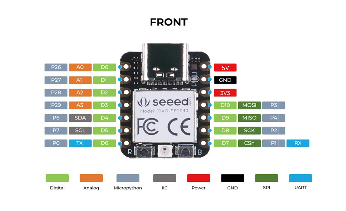
The pinout for the XIAO RP2040 is as follows (Source: Seeed Studio Wiki. When specifying pins in MicroPython, use the gray GPIO numbers.
Here, we present programming examples based on the dev board created by Shoko Kudomi, a graduate of the 2025 Fab Kab Kamakura program. Below is the schematic and PCB design for the dev board she created.


While writing a program to blink the LED connected to pin P29 on the dev board, I’ll explain how to write programs in MicroPython. First, here’s the entire code:
from machine import Pin
import sys,select,time

led_pin = 29

led = Pin(led_pin,Pin.OUT)

while True:
    led.value(1)
    time.sleep(0.5)
    led.value(0)
    time.sleep(0.5)
Write the above program in the Thonny editor.

After writing the program, press the Run button.

The LED in the top-left corner of the dev board will light up.

To save the program, press the Save button.

When prompted “Where to save to?”, select “RP2040 device”.

Save the file as “main.py”. This allows the microcontroller program to run when power is supplied, even if the Thonny editor is not open.

Coding Sample: LED Blink#
Now let’s take a look at the sample program that lights up the LED we presented earlier.
from machine import Pin
import sys,select,time

led_pin = 29

led = Pin(led_pin,Pin.OUT)

while True:
    led.value(1)
    time.sleep(0.5)
    led.value(0)
    time.sleep(0.5)
The following initial statements import modules used by the program. Note that only modules available in MicroPython can be imported here. While standard Python provides various libraries, MicroPython cannot use them.
from machine import Pin
import sys,select,time
Next, in the following section, the GPIO number (29) connected to the LED is assigned to the led_pin variable.
Then, the line led = Pin(led_pin, Pin.OUT) sets pin 29 as an output (OUTPUT).
led_pin = 29

led = Pin(led_pin,Pin.OUT)
This entry corresponds to what is known as
pinMode(D3, OUTPUT);
This corresponds to Python’s PA29 = D3.
Then, in the following while loop, the LED alternates between turning on (led.value(1)) and turning off (led.value(0)) every 0.5 seconds.
while True:
    led.value(1)
    time.sleep(0.5)
    led.value(0)
    time.sleep(0.5)
The while True: section corresponds to the loop() function in Arduino.
led.value() corresponds to digitalWrite(). A value of 1 corresponds to HIGH, and 0 corresponds to LOW.
time.sleep(0.5) pauses the program for 0.5 seconds.
This uses the time module, commonly used in standard Python. It corresponds to the delay() function in Arduino. In MicroPython, values are specified in seconds, hence 0.5(seconds), while in Arduino, values are specified in milliseconds, hence delay(500).
void loop(){

    digitalWrite(D3, HIGH);
    delay(500);
    digitalWrite(D3, LOW);
    delay(500);
}
Coding Sample: Echo#
When using USB serial communication with MicroPython, use stdin from the sys module. stdin.read(1) reads one character, and stdout.write(“—”) sends the characters in the parentheses.
Below is an example of the echo program often shown in classes, written in MicroPython. Even Arduino requires over ten lines of code to implement a similar program, but interestingly, writing it in MicroPython takes only five lines.
import sys

string = ''
while True:
    char = sys.stdin.read(1)
    string += char
    sys.stdout.write("hello.RP2040-XIAO-echo.py: you typed " + string + '\r' + '\n');
The actual execution results are as follows. Note that you cannot perform the echo-reply experiment within Thonny itself. Furthermore, if you launch a separate terminal to start serial I/O (using the usual Python miniterm), you will see an error like the one below and the port will be temporarily unavailable. This is because Thonny is already using the serial communication port with the MicroPython interpreter.
Could not exclusively lock port /dev/cu.usbmodem2101: [Errno 35] Resource temporarily unavailable
Using the screen command instead of Python’s miniterm allows you to enable echo. For example, enter the following (1000000 is the serial baud rate):
screen /dev/cu.usbmodem2101 1000000

However, in this case, communication occurs over the same serial line as the MicroPython interpreter, so echo replies may be delayed, or characters sent may not be returned.
To ensure reliable experimentation, save the above code as “main.py” on the RP2040, as shown in the blink section, then disconnect the USB cable from the PC and reconnect it. This will allow communication via Python’s miniterm as well.

Coding Sample: Button#
Using a button switch to demonstrate how to use the GPIO pin as an input.
Connect the button switch to the Dev Board as shown in the photo below: Pin 26 (top left, non-ground pin) to one side of the switch, and GND to the opposite side. Connect the wires so they cross the switch diagonally.

To read the GPIO signal, set the specified pin to IN. While button switches typically require a pull-up resistor, this code uses the RP2040’s internal pull-up resistor by adding Pin.PULL_UP.
from machine import Pin
import time

pin = Pin(26,Pin.IN,Pin.PULL_UP)

while True:

    if pin.value() == 0:
        print("Button pressed (LOW)")
    else:
        print("Released (HIGH)")

    time.sleep(0.1)
When executed, the button state is output to the serial monitor as follows. When the button is pressed, the read value is 0 (LOW). When the button is not pressed, the read value is 1 (HIGH).

Last Update 02/10/2026 by Yosuke Tsuchiya