tinyAVR 1-Series (2026 updates)#
- Author: Yosuke Tsuchiya (Fab Lab Kamakura)
- Date created: 2/8/2026
This document outlines the programming procedures for the tiny AVR series of microcontrollers. For information on the tiny AVR itself, please refer to the tinyAVR excellent documentation previously provided by Jun-san. This document includes several updates reflecting information current as of 2026.
attiny 3216 dev board sample#
I previously created a development board for the ATtiny3216. I will demonstrate the programming procedure using this development board. The schematic and circuit design for the development board are as follows. It was created around 2022. While an Autodesk EAGLE version exists, a KiCAD version has not yet been created (it will be created shortly).
PCB Design of tiny 3216 dev board.

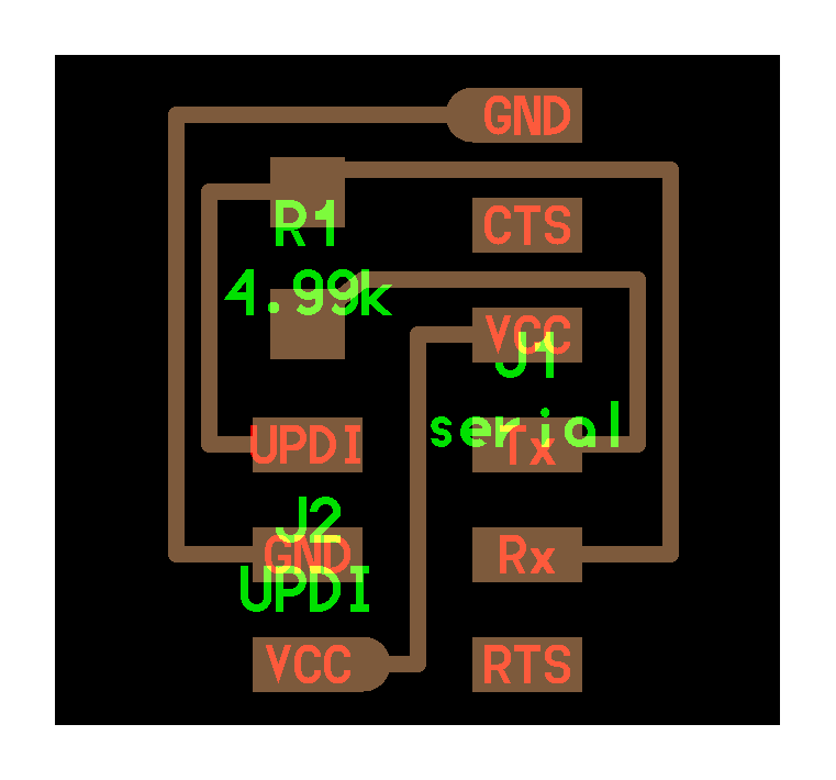
Schema of tiny 3216 dev board.

Please download the files required for fabrication from the following link.
- tiny3216 Dev board
- PCB Design,Schema by Autodesk EAGLE
- trace,interor,hole
Serial UPDI#
To write programs to the tiny AVR, we will use Serial UPDI (Unified Program and Debug Interface) here. For details on UPDI, refer to this document.
FThe Fab Academy Embedded Programming examples include a module that converts FTDI to UPDI, as shown below. Two versions are provided: a 2-pin version (UPDI and GND) and a 3-pin version (UPDI, GND, VCC). For this tiny 3216 dev board, we will use the 3-pin module.
 |
|
| 3 pin Trace Interor | 2 pin Trace Interor |
Now, we will use FTDI to write the program. The FTDI module can be purchased here, and a fabrication sample is also available on the Embedded Programming course page. Either option is acceptable. If using the 3-pin UPDI-FTDI module mentioned above, one FTDI module is sufficient. However, if using the 2-pin version, two FTDI modules are required (because the 2-pin version necessitates powering the board itself).
Since we are using a 3-pin module here, connect the board, UPDI-FTDI module, and FTDI module as shown below.
(This applies specifically to the t3216 dev board I created this time.) Please note that the VCC and GND pin locations are reversed when connecting via UPDI on this t3216 dev board. Specifically, on the dev board side, the order is VCC, UPDI, GND as shown in the diagram below. However, on the UPDI-FTDI conversion module side, the order is GND, UPDI, VCC. Be careful with the wiring.

Serial UPDI Programming Environment#
Set up the UPDI writing environment. Specifically, install Python’s pyupdi. First, install the required libraries. The following example shows the process for Ubuntu/macOS, but it should work similarly on Windows.
pip3 install intelhex pylint pyserial
Next, install directly from the pyupdi GitHub repository.
pip install https://github.com/mraardvark/pyupdi/archive/master.zip
After installing pyupdi, launch the Arduino IDE and open the Board Manager by selecting Board → Board Manager. Search for “megaTinyCore” in the Board Manager and install it.

Arduino: Test Programming#
First, perform a write test.
From the Embedded Programming course page, download the echo.ino file located in the ATTiny3216 section and open it in the Arduino IDE.
Configure the write settings as follows:
- Board: Select one that includes Attiny3216
- Port: Select the serial port connected to the FTDI. On macOS, open Terminal and choose a port like /dev/cu.usebserial-A*****. On Ubuntu (Linux), it might be /dev/ttyUSB1. Plug and unplug the FTDI module to identify the correct port.
- Chip: Select Attiny3216
- Programmer: Select Serial UPDI: SLOW: 57600 baud

Now, in the Arduino IDE, use the “Upload” button to upload the hello.t3216.echo.ino program. If it uploads successfully, output like the following will appear. If “Upload complete” is displayed, the upload was successful.
最大32768バイトのフラッシュメモリのうち、スケッチが1621バイト(4%)を使っています。
最大2048バイトのRAMのうち、グローバル変数が183バイト(8%)を使っていて、ローカル変数で1865バイト使うことができます。
SerialUPDI
UPDI programming for Arduino using a serial adapter
Based on pymcuprog, with significant modifications
By Quentin Bolsee and Spence Konde
Version 1.3.1 - Aug 2025
Using serial port /dev/cu.usbserial-A105ML9K at 57600 baud.
Target: attiny3216
Set fuses: ['0:0b00000000', '2:0x02', '6:0x04', '7:0x00', '8:0x00']
Action: write
File: /Users/yosuke/Library/Caches/arduino/sketches/3C876C9295AE5FC69B9A1A4B51CCBE71/hello.t3216.echo.ino.hex
Pinging device...
Ping response: 1E9521
Setting fuse 0x0=0x0
Writing literal values...
Verifying literal values...
Action took 0.19s
Setting fuse 0x2=0x2
Writing literal values...
Verifying literal values...
Action took 0.19s
Setting fuse 0x6=0x4
Writing literal values...
Verifying literal values...
Action took 0.19s
Setting fuse 0x7=0x0
Writing literal values...
Verifying literal values...
Action took 0.20s
Setting fuse 0x8=0x0
Writing literal values...
Verifying literal values...
Action took 0.19s
Finished writing fuses.
Chip/Bulk erase,
Memory type eeprom is conditionally erased (depending upon EESAVE fuse setting)
Memory type flash is always erased
Memory type lockbits is always erased
...
Erased.
Action took 0.06s
Writing from hex file...
Writing flash...
[                                                  ]
[===                                               ] 1/13
[=======                                           ] 2/13
[===========                                       ] 3/13
[===============                                   ] 4/13
[===================                               ] 5/13
[=======================                           ] 6/13
[==========================                        ] 7/13
[==============================                    ] 8/13
[==================================                ] 9/13
[======================================            ] 10/13
[==========================================        ] 11/13
[==============================================    ] 12/13
[==================================================] 13/13
Action took 1.25s
Verifying...
[                                                  ]
[============                                      ] 1/4
[=========================                         ] 2/4
[=====================================             ] 3/4
[==================================================] 4/4
Verify successful. Data in flash matches data in specified hex-file
Action took 0.45s
Test whether the echo.hello program has been written correctly. Insert the FTDI module into the 6-pin section of the dev board (left side of the photo) as shown below.

Launch a simple terminal (miniterm) in Python and try entering some text. miniterm is launched as follows
python -m serial.tools.miniterm <port for dev board> 115200
If it works, the example seen in Embedded Programming where input characters are displayed directly on the serial monitor will function.

Arduino: Coding Sample#
For details on the ATtiny3216, refer to the datasheet. (You’ll learn this in Embedded Programming class too, but the datasheet is the first place you should look when you want to know about a microcontroller. You don’t need to read the entire datasheet; just look up the necessary parts.)
Here, we’ll check the Pin Assignments in the datasheet. The datasheet states the following: Of the 20 pins, the top-left pin is VDD (where you input power), and the top-right pin is GND. PA0 is the UPDI write pin. PB3/PB2 are digital function only, while all other pins can be used for both digital and analog functions.

This is the pinout diagram described in the mega-tiny-core documentation. More detailed information is available in the mega tiny core repository. When writing programs for Arduino, use the orange-numbered pins in this diagram for pin assignments.

Below is a program to light up the LED connected to PA3 (pin 16 on Arduino) on the dev board. Pin 16 is set as an OUTPUT.
void setup() {
  // put your setup code here, to run once:
  pinMode(16,OUTPUT);
}

void loop() {
  // put your main code here, to run repeatedly:
  digitalWrite(16,HIGH);
  delay(1000);
  digitalWrite(16,LOW);
  delay(1000);
}

Alternatively, you can use the pin designations specified in the datasheet as follows.
void setup(){
  pinMode(PIN_PA3, HIGH);
}

void loop(){
  digitalWrite(PIN_PA3,HIGH);
  delay(1000);
  digitalWrite(PIN_PA3,LOW);
  delay(1000);
}
Using VPORT allows for faster pin I/O. Furthermore, by directly manipulating registers in a manner consistent with C language, as shown below, you can avoid including extra library programs, leading to a reduction in the overall code size. For Virtual Port, the datasheet documentation and this entry in the megatinycore repository are helpful.
void setup() {
  // put your setup code here, to run once:
  VPORTA.DIR |= (1 << 3);
}

void loop() {
  // put your main code here, to run repeatedly:
  VPORTA.IN = (1 << 3);
  delay(500);
}
C language: Test Programming#
Using the Arduino IDE makes programming relatively straightforward. However, setting up a development environment for C has become quite cumbersome lately. Even so, there are situations where developing in C offers significant advantages (the biggest being when you want to minimize program size, or when you need direct access to microcontroller features like registers). With that in mind, here’s how to set up a C programming environment for tiny AVR.
Note: This setup guide is for macOS on Apple Silicon. The steps should be similar for Linux. For Windows, the toolchain installation (like avr-gcc) will likely differ, so please research that separately.
First, install the tools needed to write AVR programs. Here, we’ll use Homebrew. Launch Terminal and execute the following:
brew tap osx-cross/avr
brew install avr-gcc avr-libc avrdude
Next, download the ATtiny Series Device Support Pack from the following Atmel website:
Download the Atmel ATtiny Series Device Support (2.0.368). The file downloads with a .atpack extension, but it’s actually a zip file. After downloading, change the extension to .zip. Then, unzip the file and rename the extracted folder. Naming it something like Attiny_DAP is recommended.
The Device Support Pack is referenced and loaded using the following C code. This explanation assumes it is placed in the location /Users/yosuke/src/Attiny_DAP.
Now, the following code is LED Blink code written in C. Save this as attiny3216-blink.c.
#include <avr/io.h>
#include <util/delay.h>

#define set(port,pin) (port |= pin) // set port pin
#define clear(port,pin) (port &= (~pin)) // clear port pin

#define LED_DIR VPORTA.DIR
#define LED_OUT VPORTA.OUT
#define LED_PIN PIN3_bm

int main(void){
  //
  // inititalize LED
  //
  CPU_CCP = CCP_IOREG_gc; // unprotect clock
  CLKCTRL.MCLKCTRLB = 0; // turn off prescalar (20 MHz)
  set(LED_DIR, LED_PIN);

  //
  // main loop
  //
  while (1){
    set(LED_OUT,LED_PIN);
    _delay_ms(1000);
    clear(LED_OUT,LED_PIN);
    _delay_ms(1000);
  }
}
- For DEVICE, specify the AVR series you are using (here, it is tiny3216)
- For PACK, specify the absolute path to the ATTiny_DEP folder
- For PORT, specify the path to the USB port you are writing to
PROJECT=attiny3216-blink
SOURCES=$(PROJECT).c
DEVICE = tiny3216
PROGDEVICE = attiny3216
MMCU=at$(DEVICE)
F_CPU = 20000000
PACK = /Users/yosuke/src/ATtiny_DFP/
PORT = /dev/cu.usbserial-A105ML9K
BAUD = 57600

CFLAGS=-mmcu=$(MMCU) -Wall -Os -DF_CPU=$(F_CPU)

$(PROJECT).hex: $(PROJECT).out
    avr-objcopy -O ihex $(PROJECT).out $(PROJECT).hex;\
    avr-size --mcu=$(MMCU) --format=avr $(PROJECT).out

$(PROJECT).out: $(SOURCES)
    avr-gcc $(CFLAGS) -I./ -I$(PACK)/include -B$(PACK)/gcc/dev/$(MMCU) -o $(PROJECT).out $(SOURCES)

pyupdi: $(PROJECT).hex
    pyupdi -d $(DEVICE) -c $(PORT) -b $(BAUD) -v -f $(PROJECT).hex

pymcuprog: $(PROJECT).hex
    pymcuprog -d $(PROGDEVICE) -t uart -u $(PORT) -c $(BAUD) -v info erase
    pymcuprog -d $(PROGDEVICE) -t uart -u $(PORT) -c $(BAUD) -v info write -f $(PROJECT).hex
Navigate to the location where the two folders are saved using Terminal, then execute the following:
make -f attiny3216-blink.c.make pyupdi
Then, the output will appear as follows. First, it follows the Makefile to perform a Compike and generate the hex code. The following shows the execution results.
avr-gcc -mmcu=attiny3216 -Wall -Os -DF_CPU=20000000 -I./ -I/Users/yosuke/src/ATtiny_DFP//include -B/Users/yosuke/src/ATtiny_DFP//gcc/dev/attiny3216 -o attiny3216-blink.out attiny3216-blink.c
avr-objcopy -O ihex attiny3216-blink.out attiny3216-blink.hex;\
        avr-size --mcu=attiny3216 --format=avr attiny3216-blink.out
AVR Memory Usage
----------------
Device: Unknown

Program:     204 bytes
(.text + .data + .bootloader)

Data:          0 bytes
(.data + .bss + .noinit)
If the hex code is generated without issues, the writing process using pyupdi will then begin according to the makefile. If compilation fails, an error will be displayed here. Should an error occur at this stage, there is a problem with the C code (the specific error will be displayed).
pyupdi -d tiny3216 -c /dev/cu.usbserial-A105ML9K -b 57600 -v -f attiny3216-blink.hex
INFO:phy Opening /dev/cu.usbserial-A105ML9K at 57600 baud
INFO:phy send 1 bytes
INFO:phy data:  : [0x0]
INFO:link STCS 0x08 to 0x03
INFO:phy send 3 bytes
INFO:phy data:  : [0x55, 0xc3, 0x8]
INFO:link STCS 0x80 to 0x02
INFO:phy send 3 bytes
INFO:phy data:  : [0x55, 0xc2, 0x80]
INFO:link LDCS from 0x00
INFO:phy send 2 bytes
INFO:phy data:  : [0x55, 0x80]
INFO:phy receive : [0x40]
INFO:link UPDI init OK
INFO:nvm Reading device info
INFO:phy send 2 bytes
INFO:phy data:  : [0x55, 0xe5]
INFO:app SIB read out as: bytearray(b'tinyAVR P:0D:0-3')
INFO:app Device family ID: 'tinyAVR'
INFO:app NVM interface: 'P:0'
INFO:app Debug interface: 'D:0'
INFO:app PDI oscillator: '3MHz'
INFO:link LDCS from 0x00

... (中略)...

INFO:phy data:  : [0x55, 0x8b]
INFO:phy receive : [0x82]
INFO:link STCS 0x0C to 0x03
INFO:phy send 3 bytes
INFO:phy data:  : [0x55, 0xc3, 0xc]
INFO:phy Closing port '/dev/cu.usbserial-A105ML9K'
(base) yosuke@ysk-M1Pro tinyAVR %
If “Closing port” appears at the end without any issues, the write operation was successful. If an error occurs during this write process, it means the write via updi failed.
C language: Coding Sample#
Here is a C language sample for the echo.ino shown in the previous Arduino code. On the attiny 3216 dev board, the serial communication pins (Tx, Rx) are connected to PB2 (Rx) and PB3 (Tx) as specified in the datasheet. Here, based on the echo.c code from t412, we modify the following sections:
- Change serial_port_direction from VPORTA.DIR to VPORTB.DIR (since we are using the PBx port)
- Change serial_port_out from VPORTA.OUT to VPORTB.OUT
- Change serial_port_in from VPORTB.IN to VPORTB.IN
- Set serial_pin_out to PIN2_bm
- Set serial_pin_in to PIN3_bm
#include <avr/io.h>
#include <util/delay.h>

#define set(port,pin) (port |= pin) // set port pin
#define clear(port,pin) (port &= (~pin)) // clear port pin
#define bit_delay_time 8.5 // bit delay for 115200 with overhead
#define bit_delay() _delay_us(bit_delay_time) // RS232 bit delay
#define half_bit_delay() _delay_us(bit_delay_time/2) // RS232 half bit delay
#define pin_test(pins,pin) (pins & pin) // test for port pin
#define bit_test(byte,bit) (byte & (1 << bit)) // test for bit set

#define serial_port_direction VPORTB.DIR
#define serial_port_out VPORTB.OUT
#define serial_port_in VPORTB.IN
#define serial_pin_out PIN2_bm
#define serial_pin_in PIN3_bm

#define max_buffer 25

void get_char(volatile unsigned char *pins, unsigned char pin, char *rxbyte) {
   //
   // read character into rxbyte on pins pin
   //    assumes line driver (inverts bits)
   //
   *rxbyte = 0;
   while (pin_test(*pins,pin))
      //
      // wait for start bit
      //
      ;
   //
   // delay to middle of first data bit
   //
   half_bit_delay();
   bit_delay();
   //
   // unrolled loop to read data bits
   //
   if pin_test(*pins,pin)
      *rxbyte |= (1 << 0);
   else
      *rxbyte |= (0 << 0);
   bit_delay();
   if pin_test(*pins,pin)
      *rxbyte |= (1 << 1);
   else
      *rxbyte |= (0 << 1);
   bit_delay();
   if pin_test(*pins,pin)
      *rxbyte |= (1 << 2);
   else
      *rxbyte |= (0 << 2);
   bit_delay();
   if pin_test(*pins,pin)
      *rxbyte |= (1 << 3);
   else
      *rxbyte |= (0 << 3);
   bit_delay();
   if pin_test(*pins,pin)
      *rxbyte |= (1 << 4);
   else
      *rxbyte |= (0 << 4);
   bit_delay();
   if pin_test(*pins,pin)
      *rxbyte |= (1 << 5);
   else
      *rxbyte |= (0 << 5);
   bit_delay();
   if pin_test(*pins,pin)
      *rxbyte |= (1 << 6);
   else
      *rxbyte |= (0 << 6);
   bit_delay();
   if pin_test(*pins,pin)
      *rxbyte |= (1 << 7);
   else
      *rxbyte |= (0 << 7);
   //
   // wait for stop bit
   //
   bit_delay();
   half_bit_delay();
   }

void put_char(volatile unsigned char *port, unsigned char pin, char txchar) {
   //
   // send character in txchar on port pin
   //    assumes line driver (inverts bits)
   //
   // start bit
   //
   clear(*port,pin);
   bit_delay();
   //
   // unrolled loop to write data bits
   //
   if bit_test(txchar,0)
      set(*port,pin);
   else
      clear(*port,pin);
   bit_delay();
   if bit_test(txchar,1)
      set(*port,pin);
   else
      clear(*port,pin);
   bit_delay();
   if bit_test(txchar,2)
      set(*port,pin);
   else
      clear(*port,pin);
   bit_delay();
   if bit_test(txchar,3)
      set(*port,pin);
   else
      clear(*port,pin);
   bit_delay();
   if bit_test(txchar,4)
      set(*port,pin);
   else
      clear(*port,pin);
   bit_delay();
   if bit_test(txchar,5)
      set(*port,pin);
   else
      clear(*port,pin);
   bit_delay();
   if bit_test(txchar,6)
      set(*port,pin);
   else
      clear(*port,pin);
   bit_delay();
   if bit_test(txchar,7)
      set(*port,pin);
   else
      clear(*port,pin);
   bit_delay();
   //
   // stop bit
   //
   set(*port,pin);
   bit_delay();
   //
   // char delay
   //
   bit_delay();
   }

void put_string(volatile unsigned char *port, unsigned char pin, char *str) {
   //
   // print a null-terminated string
   //
   static int index;
   index = 0;
   do {
      put_char(port, pin, str[index]);
      ++index;
      } while (str[index] != 0);
   }

int main(void) {
   //
   // main
   //
   static char chr;
   static char buffer[max_buffer] = {0};
   static int index;
   //
   // unprotect clock and turn off prescalar (20 MHz)
   //
   CPU_CCP = CCP_IOREG_gc;
   CLKCTRL.MCLKCTRLB = 0;
   //
   // initialize pins
   //
   set(serial_port_out,serial_pin_out);
   set(serial_port_direction,serial_pin_out);
   //
   // main loop
   //
   while (1) {
      get_char(&serial_port_in,serial_pin_in,&chr);
      put_string(&serial_port_out,serial_pin_out,"hello.t412.echo.c: you typed \"");
      buffer[index++] = chr;
      if (index == (max_buffer-1))
         index = 0;
      put_string(&serial_port_out,serial_pin_out,buffer);
      put_char(&serial_port_out,serial_pin_out,'\"');
      put_char(&serial_port_out,serial_pin_out,10); // new line
      }
   }
The makefile simply changes the first PROJECT from attiny3216-blink.c.make to attiny3216-echo.
PROJECT=attiny3216-echo
SOURCES=$(PROJECT).c
DEVICE = tiny3216
PROGDEVICE = attiny3216
MMCU=at$(DEVICE)
F_CPU = 20000000
PACK = /Users/yosuke/src/ATtiny_DFP/
PORT = /dev/cu.usbserial-A105ML9K
BAUD = 57600

CFLAGS=-mmcu=$(MMCU) -Wall -Os -DF_CPU=$(F_CPU)

$(PROJECT).hex: $(PROJECT).out
    avr-objcopy -O ihex $(PROJECT).out $(PROJECT).hex;\
    avr-size --mcu=$(MMCU) --format=avr $(PROJECT).out

$(PROJECT).out: $(SOURCES)
    avr-gcc $(CFLAGS) -I./ -I$(PACK)/include -B$(PACK)/gcc/dev/$(MMCU) -o $(PROJECT).out $(SOURCES)

pyupdi: $(PROJECT).hex
    pyupdi -d $(DEVICE) -c $(PORT) -b $(BAUD) -v -f $(PROJECT).hex

pymcuprog: $(PROJECT).hex
    pymcuprog -d $(PROGDEVICE) -t uart -u $(PORT) -c $(BAUD) -v info erase
    pymcuprog -d $(PROGDEVICE) -t uart -u $(PORT) -c $(BAUD) -v info write -f $(PROJECT).hex
If the write operation succeeds, you will obtain the same operational results as the Arduino code.

In closing#
This page demonstrates how to program a tiny AVR Series 1 microcontroller, using the Attiny3216 as an example. While Fab Academy often uses XIAO, the method shown here is becoming outdated. However, depending on the project’s scale, the tiny AVR may still be sufficient instead of using XIAO.
Last Update. 2026/02/09 by Yosuke Tsuchiya