Week 5 - 3D Scanning and Printing : Local Session#
- Authors:
Jun Kawahara,Kai Naito,Asako Okazaki,Toshiki Tsuchiyama,Georg Tremmel,Kae Nagano -
Created:
2/4/2019, Last Update:2/20/2025 - Class note
Assignments & Goal#
Group assignment#
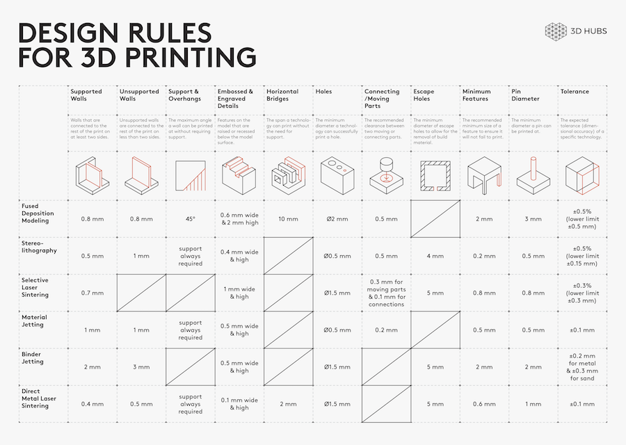
- Test the Design rules for your 3D printer(s)
Individual assignment#
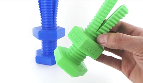
- Design and 3D print an object (small, few cm3, limited by printer time) that could not be made subtractively
- 3D scan an object, try to prepare it for printing (and optionally print it)
- File
- Include the design file.
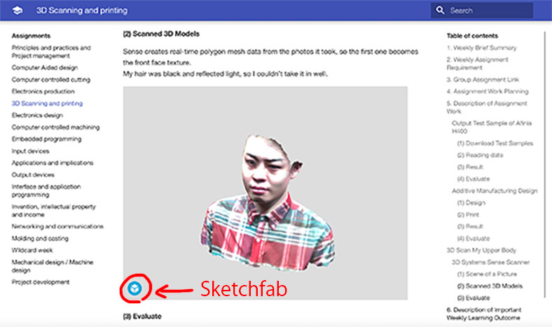
- Upload the scanned file to a service like Sketchfab, Thingiverse
Learning outcomes#
- Identify the advantages and limitations of 3D printing
- Apply design methods and production processes to show your understanding of 3D printing.
- Demonstrate how scanning technology can be used to digitize object(s)
Have you#
- Linked to the group assignment page
- Explained what you learned from testing the 3D printers
- Documented how you designed and 3D printed your object and explained why it could not be easily made subtractively
- Documented how you scanned an object
- Included your original design files for 3D printing
- Included your hero shots
Refer to Assessment page
Group Work#
Use test models to check the performance of the 3D printer in the lab. One machine is fine for the assignment. If you have time, try comparing multiple machines.
3D printer @Fablab Kamakura
- Bambu Lab P1S
- Slicer: BambuStudio
- Anycubic
- Slicer: AnycubicSlicer
- Creality
- Slicer:
Filament
- PLA
- PETG
- Bambu Filament GUide
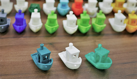
Test model
-
- Link to the STL data is in the list
-
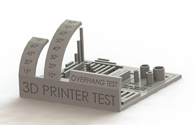
FDM Assessment Object & Protocol from Autodesk.

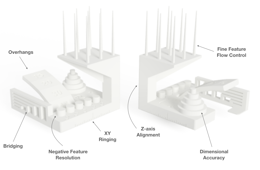
If you have enough time, try this model. This object allow you to measure:
Dimensional accuracy (backlash optional)
Negative feature resolution
Positive feature resolution/fine flow control
Basic overhang capabilities
Basic bridging capabilities
XY ringing
Z-axis alignment
- Print out the object
- Follow the protocol and measure the object
- Get the score for your printer
More details about the process and protocol at the 2021 Group Page.
Individual Work#
3D design
- Design and 3D print an object that could not be made subtractively
- support doc
- Time management is important.
3D scanner @ Fablab Kamakura
-
MIRACO by Revopoint
- Quick Start Guide : English
- 近景、遠景モードの使い方と使用シーン
- Tutorials: Revopoint Japan
- Tutorials
Other 3D scan tools
- Scaniverse: photogrammetry
- QLONE: photogrammetry
- Polycam: LiDAT 3D scanner
References#
FAQ#
Define cannot be easily made subtractively#
- Answer: Your model has undercuts, overhangs, nested parts, meshes etc.
What is an “undercut” ?#
Undercut is a feature that can make it difficult for a part to be ejected from the mold.
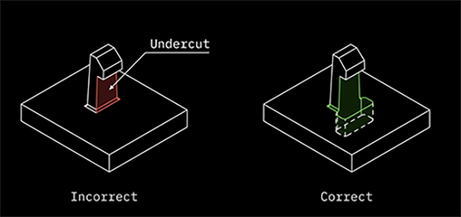
Reference:Injection Molding - Undercuts (How to Avoid and Design)
What is an “overhang” ?#
3D print overhangs are geometric shapes in a 3D model that extends outwards and beyond the previous layer.
Overhangs have no direct support on it so it is difficult to be printed.
Nonetheless, there are overhangs that are tolerable.
These are 3D print overhangs with as much as 45ᵒ angle.
But, if it exceeds this number, then issues such as droopy filament strands may be encountered.
Reference:How to improve 3D print overhangs and bridges
Reference:3D Printing Overhang: How to 3D Print Overhangs
What is “nested parts” ?#
In 3D printing, “Nested Parts” refers to the state or structure of having the same shape or type of (smaller) parts in a model.
sample photo
<Another “Nesting” meaning>
Nesting is part of a build preparation stage that optimises the use of the build volume of a 3D printer.
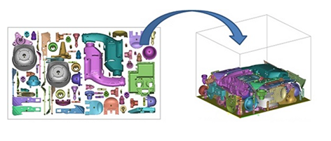
Nesting software sorts, orients and arranges 3D files to maximise space inside a 3D printer.
Nesting can be compared to Tetris, a game where you need to arrange the falling blocks of different shapes to fill the line, whereas with nesting you try to pack as many parts as possible into one 3D printer to save costs and increase machine productivity.
Nesting is most commonly used with Powder Bed Fusion (PBF) technologies, like Selective Laser Sintering (SLS) and HP’s Multi Jet Fusion (MJF).
Reference:The Role of Nesting in Polymer 3D Printing
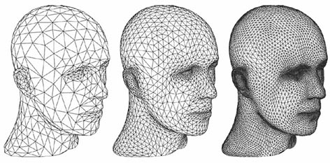
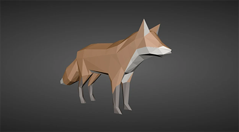
What is “mesh” ?#
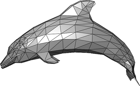
(3D) Mesh is the structural build of a 3D model consisting of polygons.
3D meshes use reference points in X, Y and Z axes to define shapes with height, width and depth.
Reference:What is 3D mesh?
Reference:Mesh vs. NURBS: Which 3D Model Is Best for 3D Printing?
ーーーーーーーーーーーーーーーーー
What is a common format for 3D printing#
- Answer: STL, OBJ or 3MF (please make your file small for the repository, compress reduce etc.)
What is “STL” ?#
STL (Standard Triangulated Language) is one of the file formats for storing data that expresses three-dimensional shapes.
It describes a set of small triangular elements that make up a three-dimensional shape, and is characterized by the fact that it only contains triangles and does not handle any other polygons or curves.
It is a standard format in the field of rapid prototyping because of its simple data structure, which does not include color or topology data (connections between shapes).
- ASCII STL
ASCII STL format is highly human readable, but the file size is larger than binary format, and it also takes longer to read and write the file.
- Binary STL
The STL also has a binary format, which is smaller in file size than ASCII and faster because there is no encoding/decoding when reading/writing.
Quote:Wikipedia
What is “OBJ” ?#
The OBJ file format stores information about 3D models.
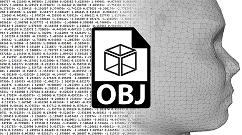
It was originally created by Wavefront Technologies for its Advanced Visualizer application to store geometric objects composed of lines, polygons, and free-form curves and surfaces.
As such, OBJs can encode the surface geometry of a 3D model but can also store color and texture information.
(※The format does not store any scene information (such as light position) or animations.)
Reference:OBJ File Format – All You Need to Know
What is “3MF” ?#
The 3MF(3D Manufacturing Format) can dethrone STL as the standard file format for additive manufacturing because it provides answers to many problems STL faces, such as limited model data storage and, frankly, low-quality files.
Designed with additive manufacturing in mind, 3MF is a handy tool that stores large amounts of model data in one small file, including:
- Full color and texture data
- Material data
- Designer’s name, part description, copyright & licensing data
- Thumbnail images
- More than one object per scene
- Support structures attached to part data
- Beam lattices
- Scene scale and measurements
- Full tray support for direct machine preparation
- Printer configuration information
- Data encryption
- Volumetric Design (coming soon)

All of this seems like it would produce massive files, but 3MF files use the same compression method as the popular ZIP format, which makes 3MF files lightweight and small in file size (typically half to a third the size of an STL file of the same model).
This also means that you can easily decompress the file to work on the contained data, just like a ZIP.
Reference:3MF File Format – All You Need to Know
Should I include my scanned file(s)#
- Answer: Not necessary, files can be very large
If the file size is large, please use an external site such as Sketchfab or GitHub to upload the data.
Advice from Instructors#
- Pay special attention to time management this week.
- 3D printers take a long time to form. Also, they do not always print well.
In the case of printers without enclosures, the printing environment (temperature and humidity) will also affect the probability of success.
- Also, if you use filament that has been moistened by moisture, printing may fail.
Reference:How does water taken into filament behave during modeling?(JP)
- Creating with a 3D printer is always a trial and error process.
Make a schedule based on the assumption that you will have to repeat output, data modification, and parameter adjustment several times before you succeed.
Reference:3 Easy Fixes for 3D Printed Warpage (PLA, PETG, ABS)(JP)
Reference:3D Printing Troubleshooting All Common Problems
- It is a good idea to keep the printer running at all times.
-
Assignments made by individual assignment must be in a form that can only be made by an additive manufacturing process.
Reference:Additive vs. Subtractive Manufacturing
How to investigate the characteristics and performance of 3D printers#
※ Please look for other sample data and reference sites regarding 3D printer characteristics and performance research. (Pitch and material differences, etc.)
※ There are more test samples, so look for them and print them out.
Reference:3D Printer Test Print: Best Torture-Test Models of 2021
ーーーーーーーーーーーーー
Subtractive Manufacturing and Additive Manufacturing#
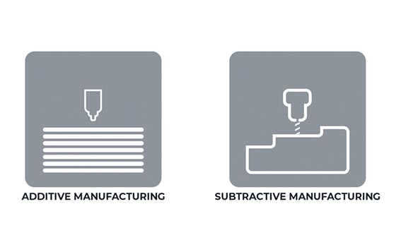
What is subtractive manufacturing?#
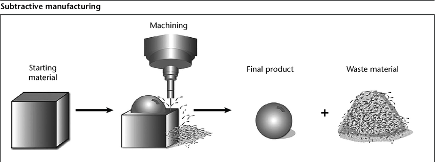
This is a manufacturing method that involves cutting and trimming materials as in conventional cutting processes.
In the subtractive manufacturing method, the material is cut and processed, so all the cut parts become waste.
In additive manufacturing, the necessary materials are piled up, so there is little waste of materials.
It is not only eco-friendly, but also reduces material costs and processing time.
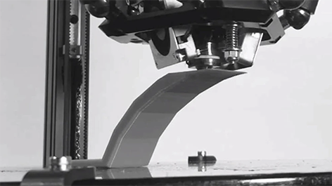
What is additive manufacturing?#
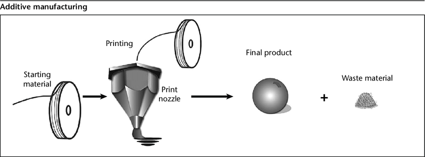
It is a manufacturing method in which materials are built up from scratch, and manufacturing using 3D printer output is a typical example of additive manufacturing, or is treated as almost synonymous with it.
It has the following four features.
・Can respond immediately to changes in specifications, etc.
・Reduction of material and processing costs
・Can create designs that could not be created with conventional cutting processes.
・Quick turnaround from design to completion
For 3D printing output, there are also methods such as topology optimization and generative design.
These are methods to design an optimal shape by setting conditions such as load and the space where an object can exist.
Differences between the two manufacturing methods#
In cutting processes, there are situations where the ideal design cannot be realized because the blade cannot fit or the workpiece cannot be fixed.
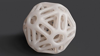
With additive manufacturing, there are no such constraints, so it is possible to design the ideal shape.
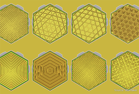
The internal structure can be made lighter by using a lattice structure with hollow or perforated parts, or multiple parts can be designed as a single part.
The design method for maximizing additive manufacturing is called DfAM (Design for Additive Manufacturing).
What is DfAM(Design for Additive Manufacturing)?#
Design for Additive Manufacturing is an acronym that refers to a design method for maximizing the use of additive manufacturing.
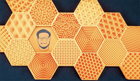
There are many ways to do this, such as using a honeycomb structure for the internal structure to reduce weight, creating a shape that could not be machined by cutting, combining multiple parts into one, and changing the angle at which the 3D printer support is attached to prevent the support from being attached.
Quote:Additive Manufacturing, a lean manufacturing method|Explaining the features and benefits(JP)
ーーーーーーーーーーーーー
3D scanning of the object (optional printing is available)#
What is 3D scan?#
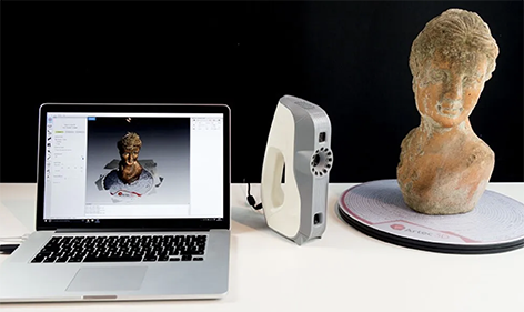
3D scanning is the process of analyzing a real-world object or environment and collecting data on its shape and possibly appearance (such as color).
The collected data is then used to build a digital 3D model.
3D scanners are based on a variety of technologies, each with its own limitations, advantages, and costs.
There are still many limitations in the types of objects that can be digitized. For example, optical technologies can encounter many difficulties, such as dark, shiny, reflective, or transparent objects.
For example, industrial CT scanners, Structured Light method 3D scanners, LiDAR, and Time Of Flight 3D scanners are capable of building digital 3D models without destructive testing.
Quote:Wikipedia
If we divide 3D scanning methods into two major categories, I think we can divide them into photogrammetry, which creates a 3D model from a photograph, and LiDAR scanning, which uses a laser beam.
What is photogrammetry?
#
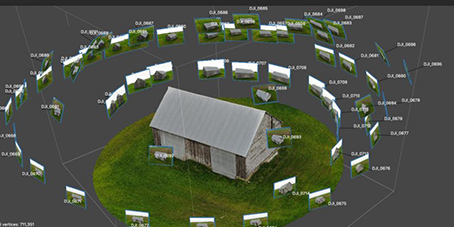
This is a method of creating a three-dimensional 3DCG model by shooting a subject from various angles and analyzing and integrating the digital images.
What is LiDAR scan?
#
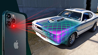
LiDAR (short for Light Detection and Ranging) is a method of measuring the depth of the space to which the camera is pointed and the 3D shape of the subject by measuring the time it takes for light emitted from the sensor to hit an object and bounce back, thereby identifying the distance to and size of that object.
LiDAR scanning became a hot topic when it was incorporated into the iPad Pro released in March 2020, the iPhone 12 Pro released in October 2020, and the iPhone 12 Pro Max released in November 2020.
-
LiDAR scanning softwares
ーーーーーーーーーーーーー
settings & troubleshooting guides#
- Print Quality Troubleshooting Guide - SIMPLIFY3D
- 3D Printing Troubleshooting 41 Common Problems in 2019 - All3D
- Clint’s Simplify3D Settings Manual
- 3 Easy Fixes for 3D Printed Warpage (PLA, PETG, ABS)
- 3D Printing Troubleshooting All Common Problems
ーーーーーーーーーーーーー
Other Reference Websites#
-
Is it realistic to melt down 3D printer failures and reuse them?(JP)
-
Can you make transparent parts with a 3D printer?(youtube/JP)
-
Introduction to Open Source 3D Printers to Watch in 2022(JP)
-
Building an Epic DIY 3D Printer: Voron 2.4 with Mods!(youtube)
-
Microsoft’s New Method for Generating 3DCG from 2D Images(JP)
-
Free Multi Color Printing on Ender 3 without special Hardware(youtube)
-
How much does it cost to prototype filament for a 3D printer?(JP)
-
Furniture made from coffee grounds! 3D printing project to recycle waste materials(JP)
-
A toy with a spring mechanism made with a 3D printer is too much!
-
YOU MAWO: scanning, 3D printing & finishing the key to custom eyewear
-
3D Printing Without Support Structures, On a Bed of Multiple Tiny Elevating Squares
ーーーーーーーーーーーーー
Other 3D printers (not in the lab now)#
Afinia H800+#
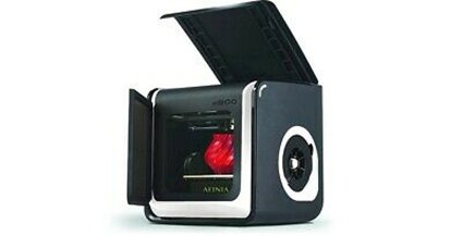
- build volume: 255(W) × 205(D) × 205(H) mm
- manuals & guides
- download: afinia studio
Prusa i3 mk3#
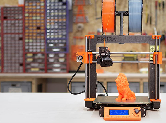
- build volume: 25 cm x 21 cm x 21 cm
- user manual: English
-
download: PrusaSlicer 2.1.1
Reference:Shave off some printing time! Slice Settings Tuning with PrusaSlicer(JP)
Reference:Ironing setup using 3D printer Prusa i3
- What is Ironing?・・・
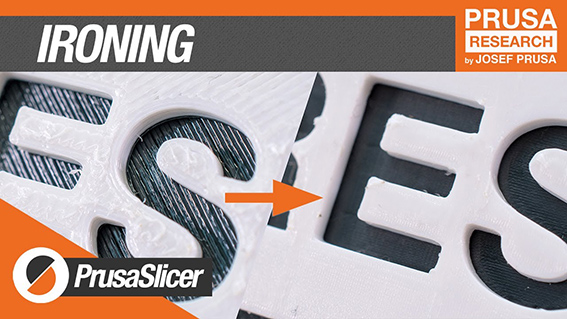 Ironing is a technique for smoothing the top surface of a 3D printed model to give the part a cleaner look.
Theoretically, ironing a 3D printer is very similar to ironing clothes.
Just as the heat from the iron is used to stretch out the wrinkles in the clothes, the 3D printer uses the heat from the nozzle to stretch out the irregularities in the final layer (surface).
As this happens, a small amount of material is extruded from the nozzle onto the surface. The heat from the nozzle softens the layer, and the extruded material can easily fill in the gaps in the layer and make it smooth.
Since the nozzles of most 3D printers are pointing downward, ironing can only be done on the final layer (top surface) of the model.
Reference:PrusaSlicer: Ironing – How to Get a Smooth Surface
- What is Ironing?・・・
Prusa i3 mk3#
- build volume: 25 cm x 21 cm x 21 cm
- user manual: English
- download: PrusaSlicer 2.1.1
Links#
ーーーーーーーーーーーーー
Support documents#
ーーーーーーーーーーーーー