Molding & Casting Week - Mold Making Tutorial in Fusion360#
by Rico Kanthatham, FabLab Kamakura May 14, 2020
This is a quick tutorial on how to use Fusion 360 to 3D model a 2-part ‘Mold of Mold’. The model can be used in a CAM software to generate a 3D toolpath for milling ‘Mold of Mold’ out of wax on a CNC machine. Knowledge of basic Fusion360 functionality is required.
A Simplified Overview of the Mold Modeling Procedure#
This tutorial will help you to make a ‘Mold of Mold’ 3D model by reverse engineering it from the ‘Final Object’ to be cast.
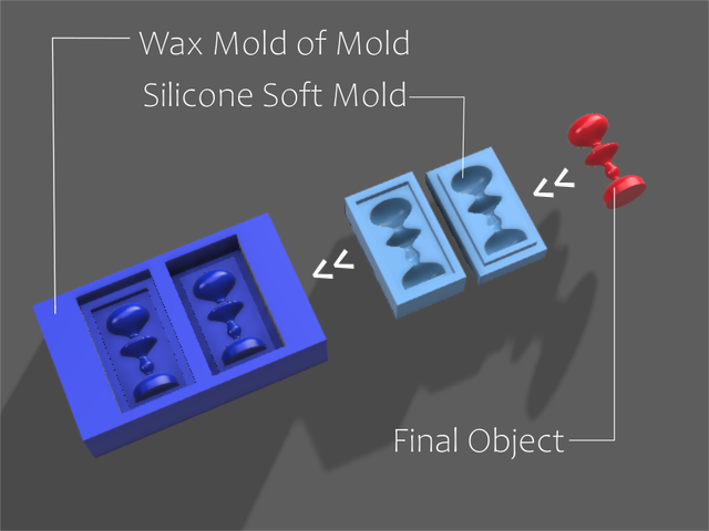
We will start with a 3D model of the ‘Final Object’…the red chess piece in the image below. Will will use this ‘Final Object’ to make the next 3D model object, which is a 2-part ‘Soft Mold’…shown as the light blue objects in the image. Lastly, we will take the 3D model of the ‘Soft Mold’ and use it to make a 3D model of the final wax ‘Mold of Mold’ (the dark blue object below)…which is what we will use in a CAM software to generate a 3D milling toolpath for CNC milling of a real wax block.
1. ‘Final Object’ >> 2. ‘Soft Mold’ >> 3. ‘Mold of Mold’
Modeling Work Strategy in Fusion360#
In Fusion360, you will 3D model all 3 objects described above in the following order… one model making the next in succession.
- Final Object…this 3D model will only be used to make the ‘Soft Mold’ 3D model.
- Soft Mold…this 3D model will only be used to make the ‘Mold of Mold’ 3D model.
- Mold of Mold…this 3D model will be exported to a CAM software to generate a 3D toolpath for use by the milling machine to mill the wax block material.
Step 1 - Model The Wax Block#
Actually, there is a preparation step…
we will first make a 3D model of the ‘Wax Block’, which will be used as a real-world, real-dimensions, boundary reference for the ‘Soft Mold’ and the ‘Final Object’ we will make.
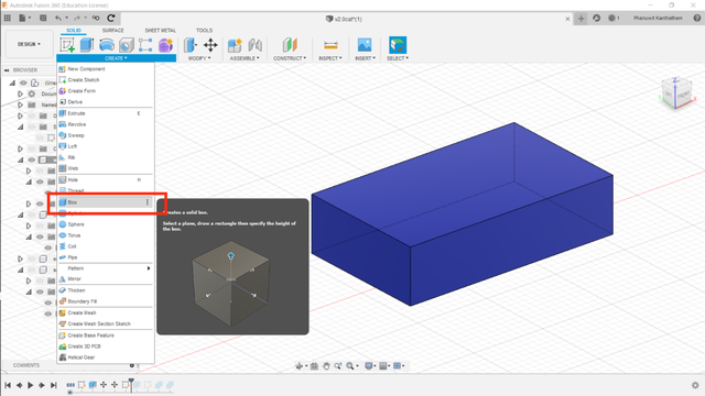
Modeling: 3D model the ‘Wax Block’ by using Fusion360’s ‘Solid Box’ modeling tool…inputting the real-world dimensions 147mm for length, 88mm for width and 37mm for height.
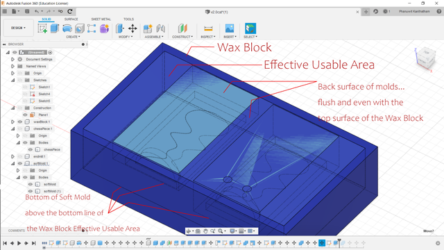
Important: Effective Usable Dimensions While the ‘Actual Dimensions’ of the wax block used for the assignment is 147mm x 88 mm x 37mm (dark blue outer area). But the ‘Effective Usable Dimensions’ of the wax block (light blue inner area) is approximately 135mm x 75mm x 30mm.
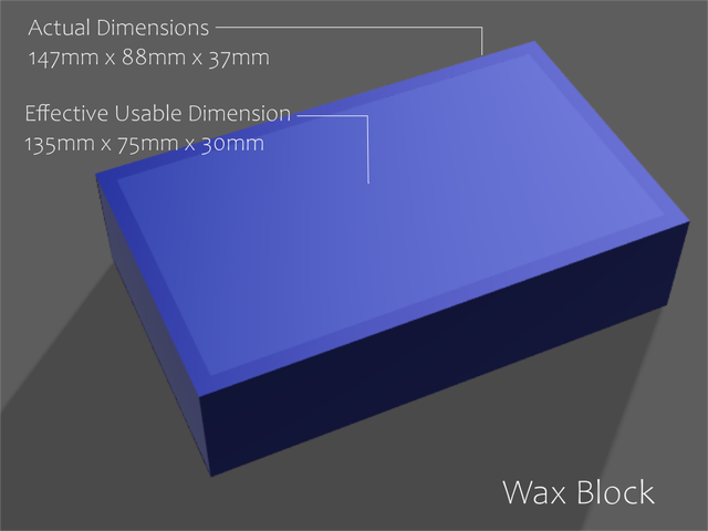
This is because pragmatically, you cannot mill all the way to the sides or bottom of the wax block.
A margin of wax material must be maintained on the sides and bottom of the wax block…to contain the silicone casting material that will be poured into the wax ‘Mold of Mold’.
Let’s move on to the next step and make our ‘Final Object’ model…
Step 2 - Model The Final Object#
Since we are reverse engineering the target ‘Mold of Mold’, we start first by modeling the desired ‘Final Object’. You can model (almost) ANY object you wish for casting, but there are some ‘limiting conditions’ you must take into account.
There are limitations inherent to 3-axis CNC milling, a subtractive process where the cutting endmill approaches the stock material primarily from the top (Plunge Cut) and side (Side Cut)…but cannot approach from the bottom.
Therefore, your ‘Final Object’ design…
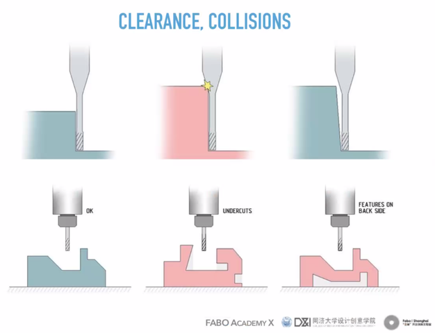
- Cannot have any ‘Undercut’ areas…the endmill cannot reach these areas
- Cannot have any ‘Bottom Features’…the endmill cannot reach these areas
- Should not require too deep milling…the endmill shank or spindle collet may collide with the stock material (wax block in this case)
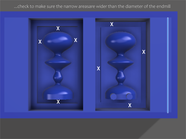
- Cannot have cut areas narrower than the endmill diameter”…do not have grooves, channels, spaces between 3D features that are less than the diameter of the endmill
When designing your ‘Final Object’… you must be well aware of the endmill’s cutting diameter and cutting length. Know before you design your ‘Final Object’ what endmill you will use.
Important: Some of the limitations described above can be ‘solved’ by doing 2 (or more) part molds.
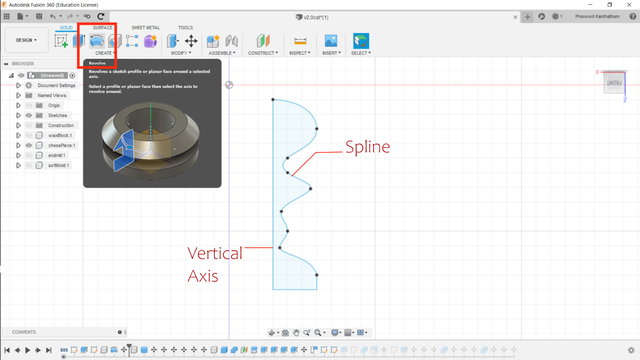
Here is an example of a slightly complex ‘Final Object’ that can be made with a 2-part mold…

Modeling: This 3D object was made by applying the ‘Revolve’ operation a ‘Spline’ profile (drawn in the sketch workspace) around a ‘Vertical Axis.
The ‘Final Object’ is made, now we can make the ‘Soft Mold’…
Step 3 - Model The Soft Mold#
Using the 3D model of the ‘Final Object’, a 3D model of the ‘Soft Mold’ can be made relatively easily. Briefly, we will be primarily using a combination the ‘Solid Box’, ‘Boolean Cut’ and ‘Split Body’ operations to make the ‘Soft Mold’ 3D model object. The detailed procedure as follows…
1. Make a Solid Box around the Final Object#
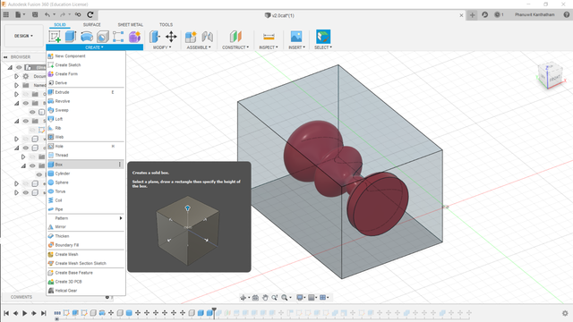
Modeling: Use the ‘Solid Box’ tool under the ‘Construct’ Menu.
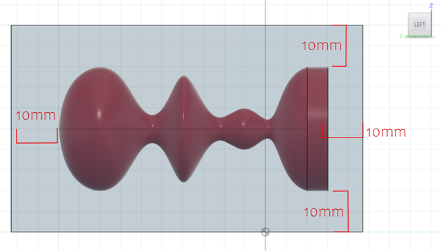
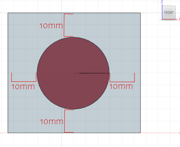
It is important the box is bigger than the ‘Final Object’ by approximately 10mm on ALL sides. The ‘Final Object’ should float in the box with 10mm of space above, below and to the sides of it.
2. Create a Cavity inside the Solid Box#
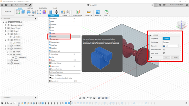
In this step, the ‘Final Object’ will be used to cut a cavity in the middle of the ‘Solid Box’ using a Boolean operator.
Modeling: Using the ‘Combine’ operation in the ‘Modify’ menu…choose the ‘Solid Box’ as the ‘Target Body’ and the ‘Final Object’ as the ‘Tool Body’. Also choose ‘Cut’ from the ‘Operation’ menu and check ‘Keep Tools’ to avoid deletion of the ‘Final Object’.
3. Split the modified Solid Box in half using the Split Body operator#
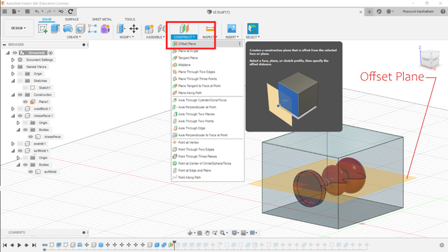
With an internal cavity created in the middle of the ‘Solid Box’ (a void in the shape of the ‘Final Object’), we will cut it in half using the ‘Split Body’ tool. An ‘Offset Plane’ will be created and used as the cutting tool for the modified ‘Solid Box’.
Modeling: Turn off the ‘Final Object’ from view by clicking the eye icon next to the object name. From the ‘Construct’ menu, choose ‘Offset Plane’, select the top surface of the modified ‘Solid Box’ and enter a ‘Distance’ from the top surface at approximately the middle point of the ‘Final Object’.
Modeling: Now from the ‘Modify’ menu, select the ‘Split Body’ tool and split the modified ‘Solid Box’ into two pieces…choose the modified ‘Solid Box’ as the ‘Body to Split’, the ‘Offset Plane’ as the ‘Splitting Tool(s)’ and make sure the ‘Extend Splitting Tools’ checkbox is checked. Clicking ‘OK’ to complete the operation.
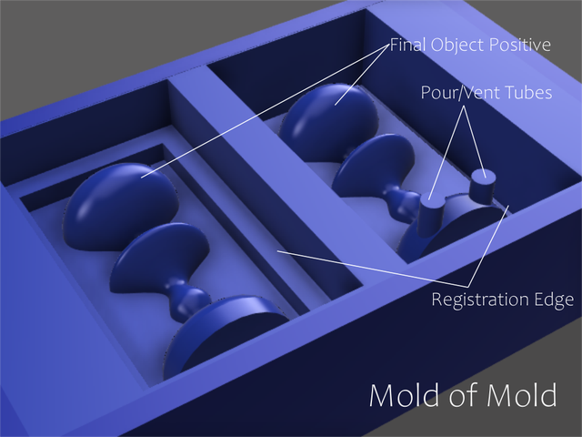
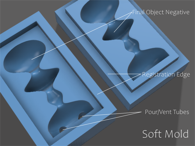
4. Add a Registration Edge#
With the ‘Solid Box’ split into 2 parts, we will add a ‘Registration Edge’. The purpose of the ‘Registration Edge’ is to make the alignment of the top and bottom mold parts, when put together, perfect every time.
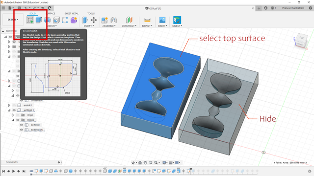
Modeling: Select the top part of the 2-part ‘Solid Box’, rotate it 180 degrees along the Y-axis to reveal the inner cavity made by the ‘Final Object’. Choose one of the 2 halves (it doesn’t matter which one), select the top surface with the ‘Final Object’ negative cavity and enter the ‘Sketch’ workspace.
Modeling: Using the ‘Offset’ tool, select the outer most edge of the top surface and offset the perimeter inwards -50mm or more.
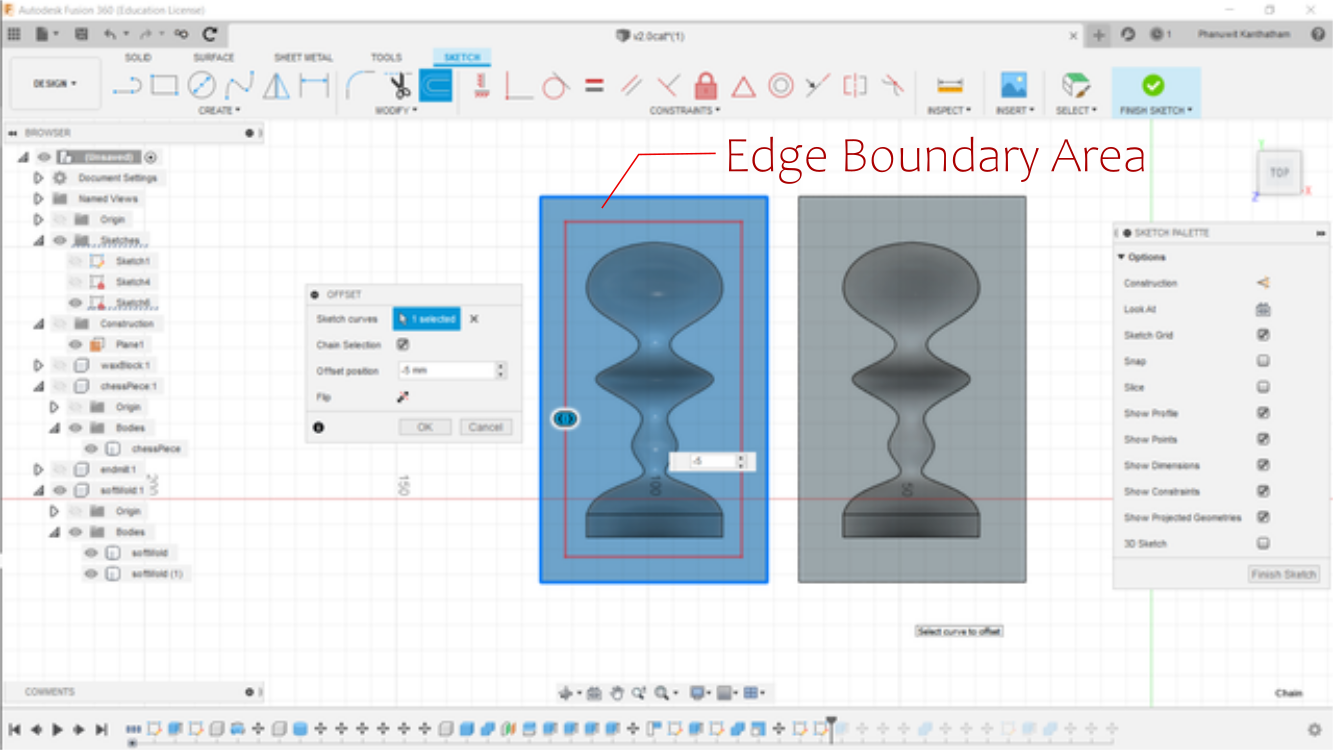
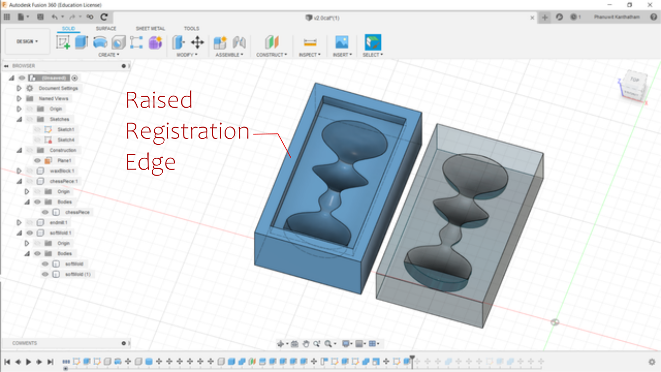
Modeling: Select the newly created 5mm border area and use the ‘Extrude’ command to raise the boundary edge 50mm (or more).
We will use this new, raised ‘Registration Edge’ to cut a corresponding ‘Registration Edge’ on the other half of the mold.
Modeling: Rotate the top half of the mold with the raised ‘Registration Edge’ back on top of the bottom half of the mold. Select the ‘Move’ command using the ‘Point to Point’ method…to choose two corresponding corners of the cavities on the two halves…to ensure perfect alignment of the ‘Final Object’ cavity.
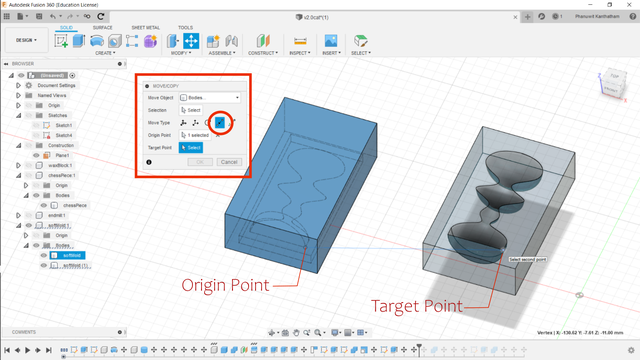
Important: When done correctly, the outer edges AND and the inner cavity edge of the top and bottom halves of the mold should align perfectly. It is VERY important that this step is done correctly…before moving to the next step.
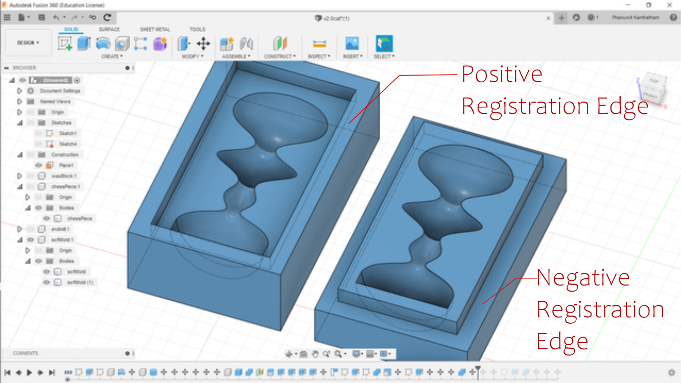
Modeling: Making sure that the top and bottom mold alignment is correct…use the ‘Combine’ tool in the ‘Modify’ menu, select the bottom half of the mold as the ‘Target Body’ and the top half of the mold (with the raised ‘Registration Edge’) as the ‘Tool Bodies’. Also choose ‘Cut’ operation and check the ‘Keep Tools’ checkbox. Click ‘OK’ to cut a ‘Registration Edge’ on the bottom half of the mold.
Rotating the top half of the mold again…shoud reveal that there are complementary ‘Registration Edges’ on both halves of the mold.
The ‘Soft Mold’ is nearly done!! Next…
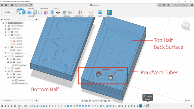
Adding Pour and Vent Tubes#
A ‘Pour Tube’ (where we will pour in the casting material) and a’Vent Tube’ (to allow air to escape when material is poured into the Pour Tube) will be added to the top half of the mold.
Modeling: Selecting the back, outer surface of the mold (opposite to the cavity surface), enter the ‘Sketch’ workspace. Choosing a suitable location (where the cavity comes closes to the back surface and where the scar from tube removal would be least unattractive on the ‘Final Object’)…draw 2 circles 5mm or more and extrude down into the ‘Final Object’ cavity, cutting 2 tubes.
One tube will be used to pour casting material in…while the other will allow air to escape.
The ‘Soft Mold’ is now complete! Next, we use this mold to make the next ‘Mold of Mold’…
Step 4 - Make the Mold of Mold Model#
The final step to make the ‘Mold of Mold’ model that will be used to create the toolpath to mill the wax block is relatively quick and easy to do (after the more challenging first few steps). Basically, we will use the ‘Soft Mold’ halves we just made and subtract it from the ‘Wax Block’ model we made in Step 1.
The most challenging part of this step is ensuring that the ‘Soft Molds’ will fit within the ‘Effective Usable’ area we defined in the ‘Wax Block’ earlier (i.e. fit within the 135mm x 75mm x 30mm inner area). To check this, simply flip both halves of the ‘Soft Mold’ over (so that the back surface, not the cavities, are facing upwards) and drag it inside the ‘Effective Usable’ area of the ‘Wax Block’.
Important: Make certain that the back surface of the ‘Soft Mold’ is flush and even with the top surface of the ‘Effective Usable’ area of the ‘Wax Block’. Move the ‘Soft Mold’ in the XY directions until it sits comfortably within the ‘Effective Usable’ area of the ‘Wax Block’.
Modeling: When the position is satisfactory, run the ‘Combine/Cut’ command similar to Step 3…choosing the ‘Wax Block’ as the ‘Target Body’ and the 2 ‘Soft Molds’ as the ‘Tool Bodies’, making sure again that the ‘Keep Tools’ checkbox is checked.
The ‘Mold of Mold’ is done!!!…and ready to be exported to a CAM software for toolpath generation.