VCarve Tutorial#
Author: Yosuke Tsuchiya, Shoko Kudomi, Fab Lab Kamakura
Last Update: 2026/03/04
VCarve is a general CAM Software. In Fab Academy, VCarve mainly used for making CAM Path of Shopbot. There are two PCs that are installed VCarve in Fab Lab Kamakura. This document introduce basic procedure to make CAM file for shopbot.
Before this task, you should finished to make a design file by CAD software.
1. Job Setup#
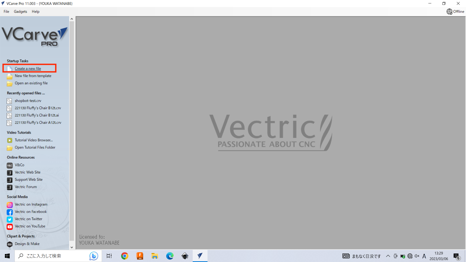
First, select “Create a new file” to start.
And you can find the “Job Setup” panel on the left side.
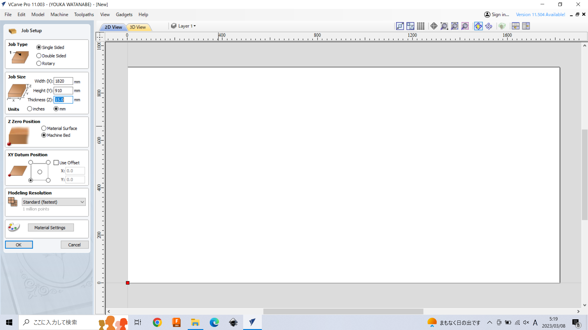
Job Type: choose “Single Sided”.
Job Size: Set your material size of width, height, thickness. For example, if you use “Softwood plywood 15mm thickness 910x1820mm”, set width: 1820.0, height: 91.0, thickness: 15, then select the “unit” as “mm”.
Z Zero Position: This is very important. Here, choose “Machine Bed” (In case if you adjust the Z-Origin of Shopbot on the machine bed). If you adjust the Z-Origin on the material, choose “Material Surface”. Fab Lab Kamakura’s basic rule choose “machine bed”.
XY Datum Position: You don’t need to set here.
After setup is fihished, click “OK”.
2. Drawing#
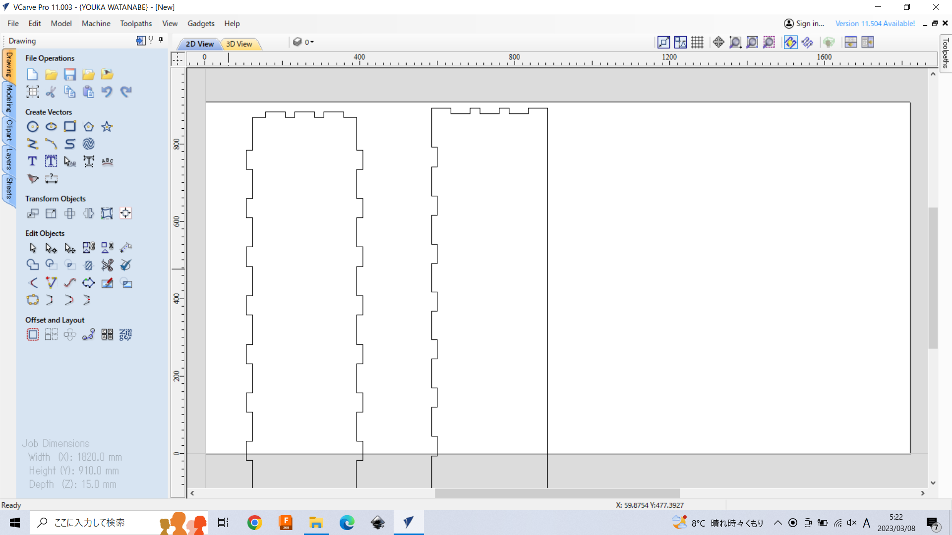
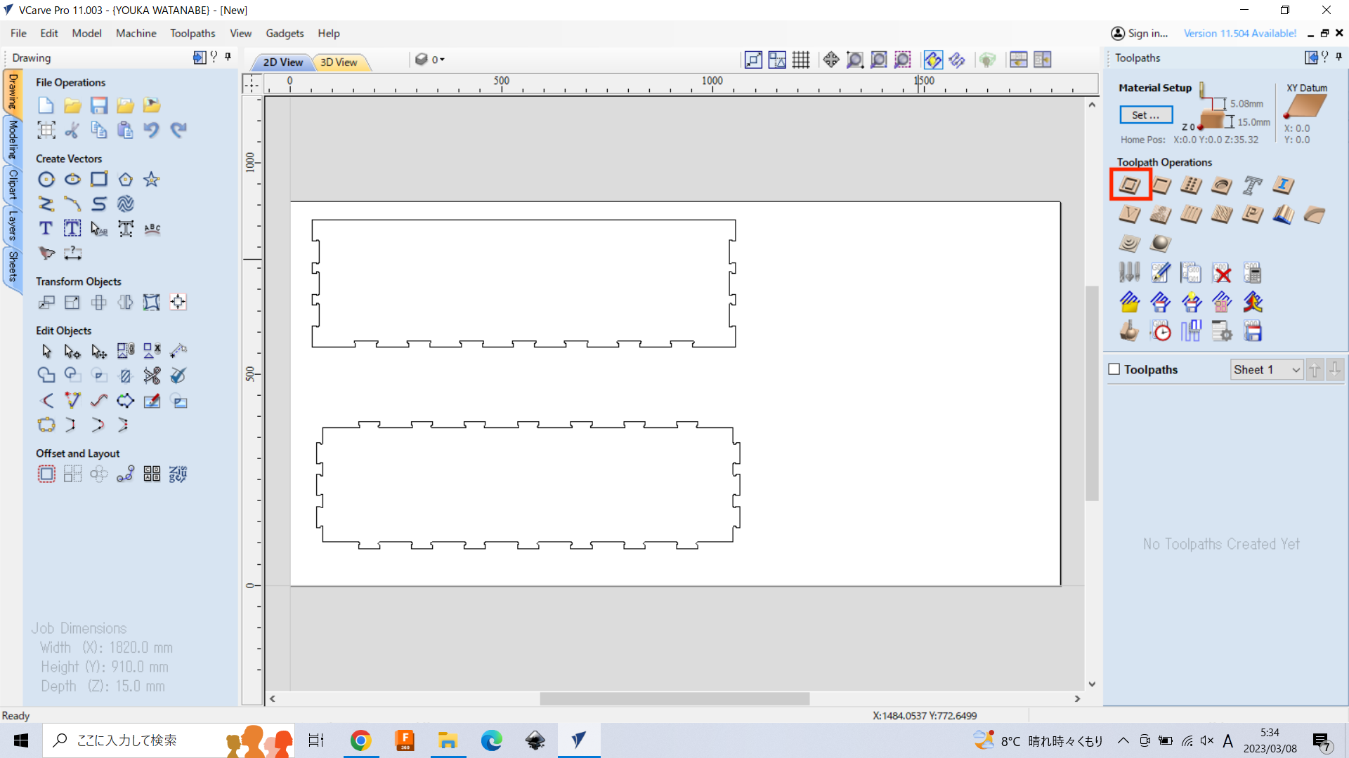
After Job setup finished, you can see the drawing view as below. To import what you designed, select “Import Vectors”. Make sure your design file should be imported 2D Vector format (like svg, dxf, ai…).

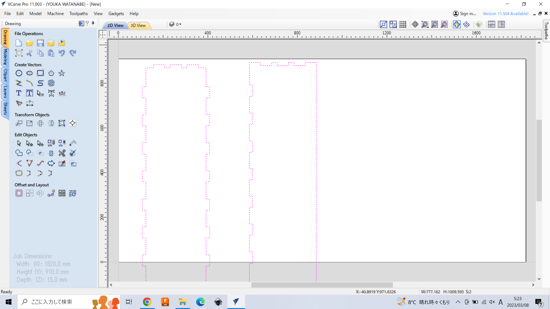
Here, I imported my design file of my shopbot session assignment (2019)
Move and Rotate
Click imported object, then the path turned into purlpe doted line. Pushing Shift key and click, you can select multiple objects at the same time.
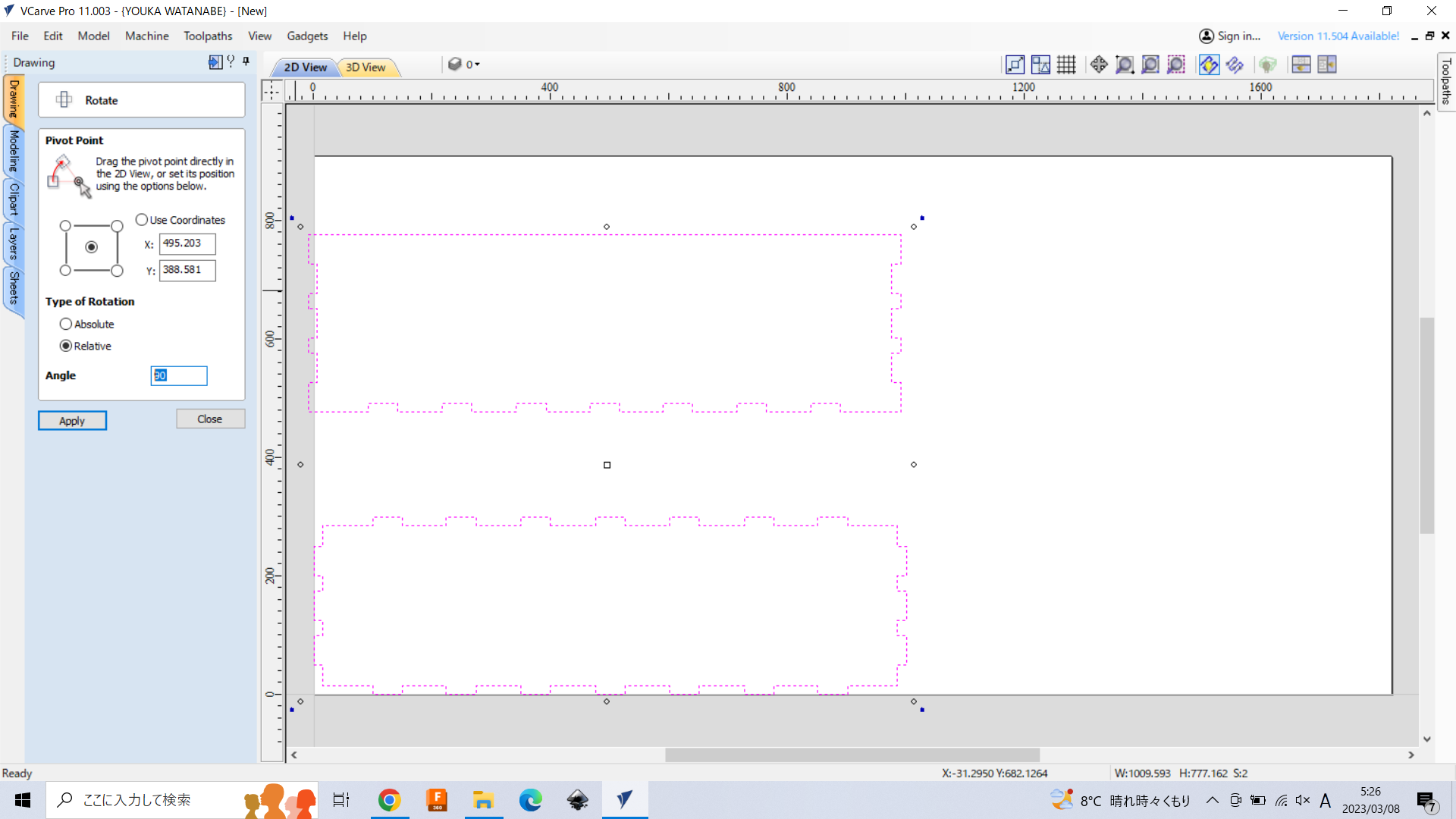
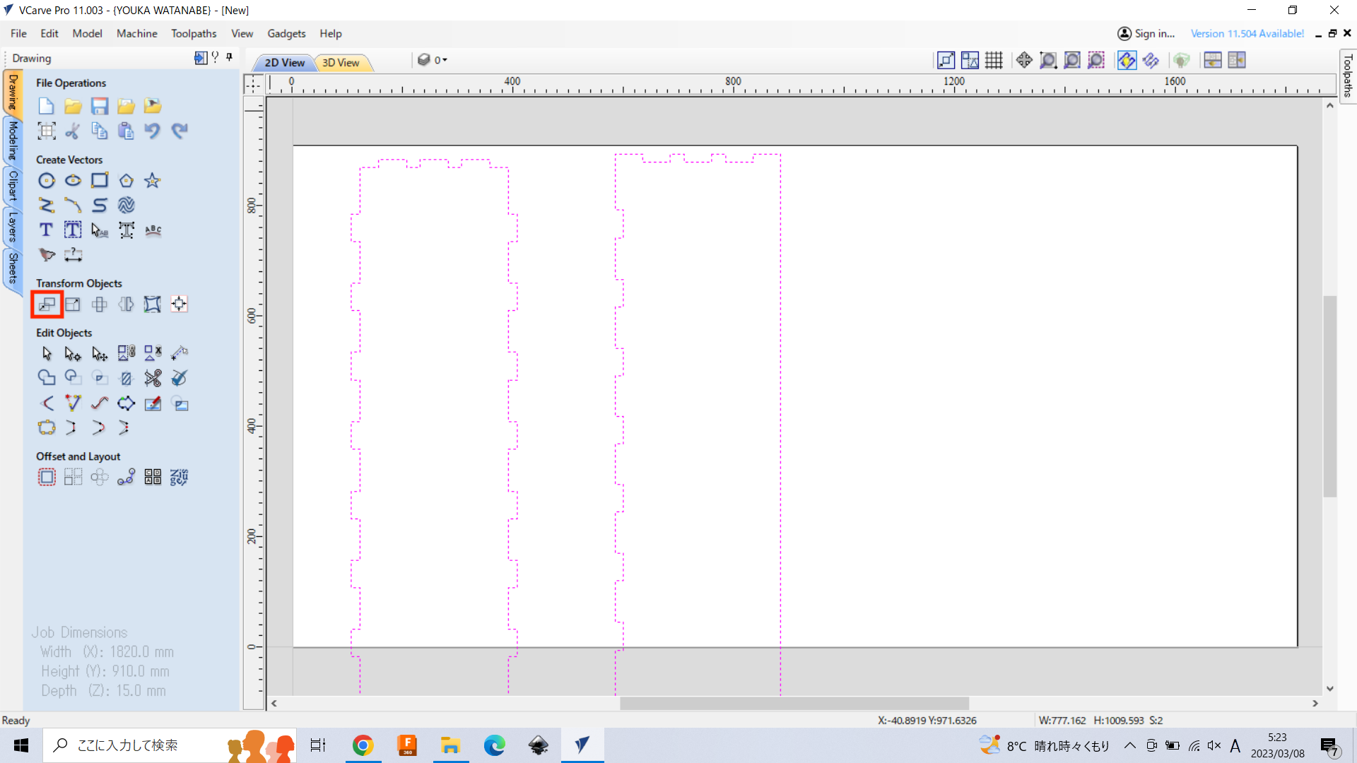
To rotate the objects for keeping in range of job size, click “rotate selected object” button.

Drag the corner or input the num of rotate in “Angle”, then the objects are rotated.
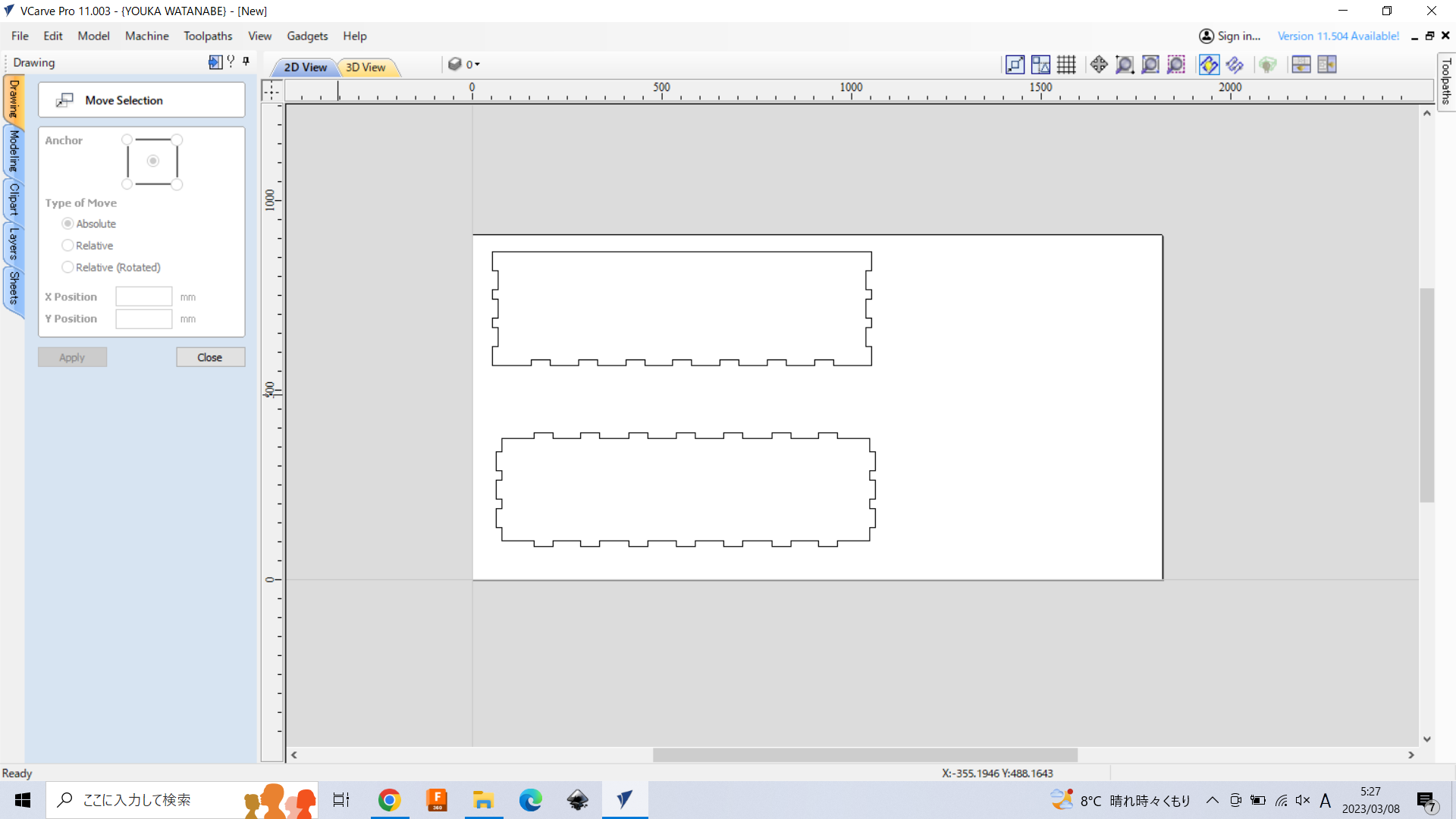
If you want to move the objects, click “Move” button.
(オブジェクトをダブルクリックする事でも移動可能。端以外を選択し移動。)
Drag the objects or put the num into X or Y, then object will move.
Array
同じ形状を複数切る場合は、Arryメニューから複製も可能。タブ、Filletも複製できる。
複製したい行数・列数、間隔を指定
※木目に沿って並べること
Fillet (T-bone)
To add the fillet, click “Fillet - create fillets between two spans” button.
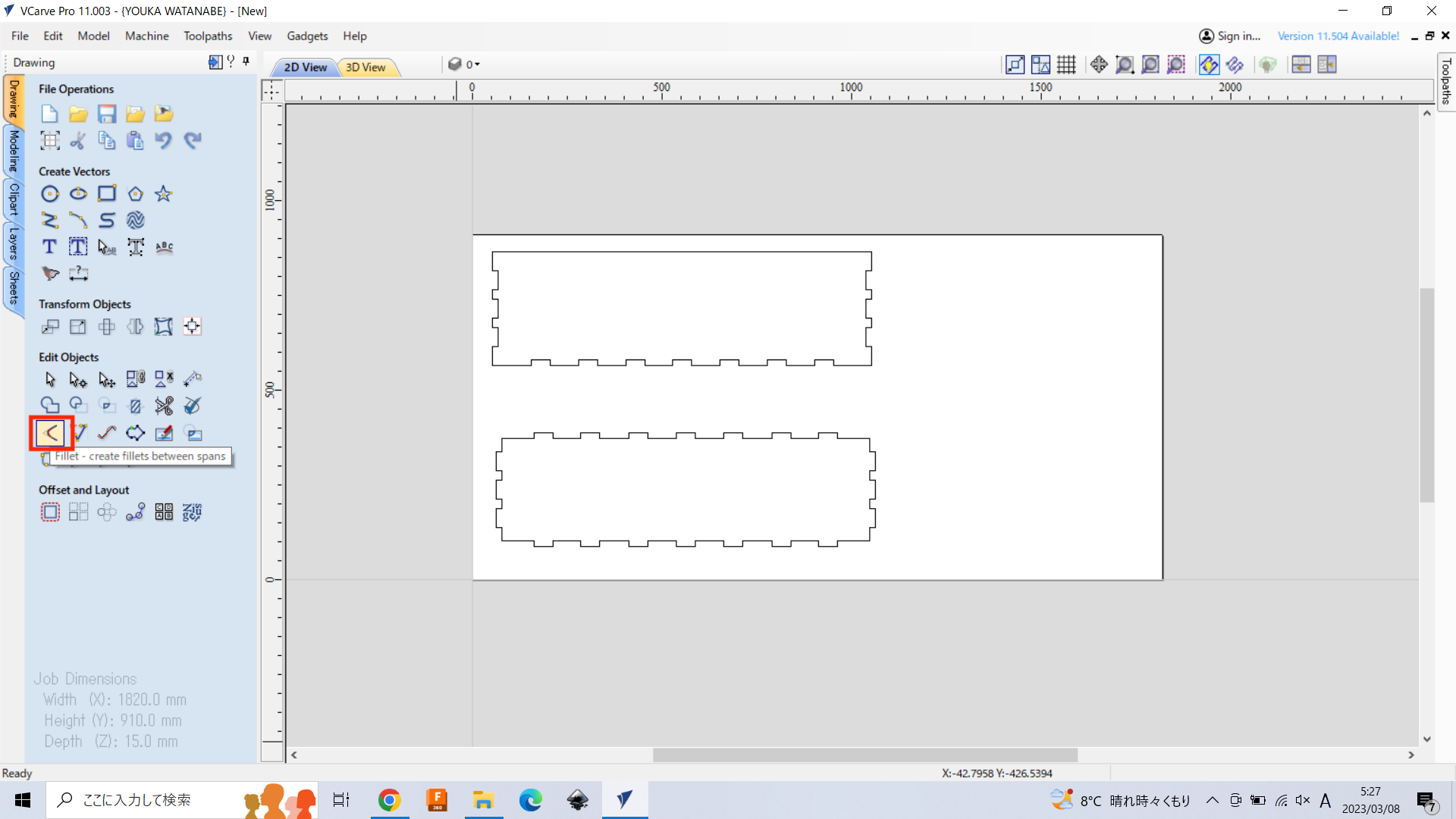
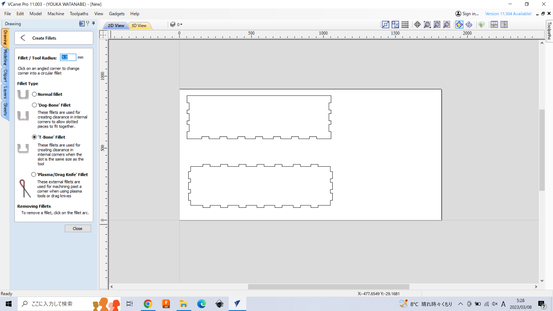
“Fillet / Tool Radius” put the size of tool radius size. Here, we use this type of endmill in the lab, and radius size is “3.175 mm”.
Filletはツール半径で設定。鎌倉のラボのミルの場合3.175mm
※Fusionにてデータに含める事も可。
“Fillet Type” choose any type you want. The recommendation is “T-Bones Fillet”.
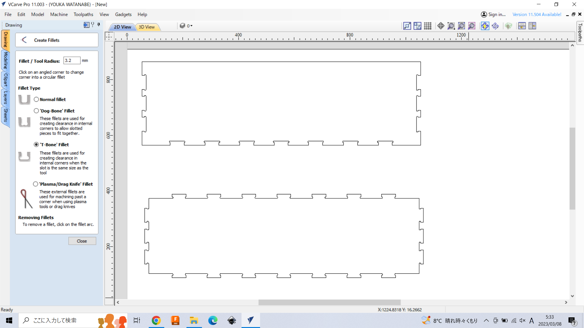
Then, click the positions that you want to add fillet.
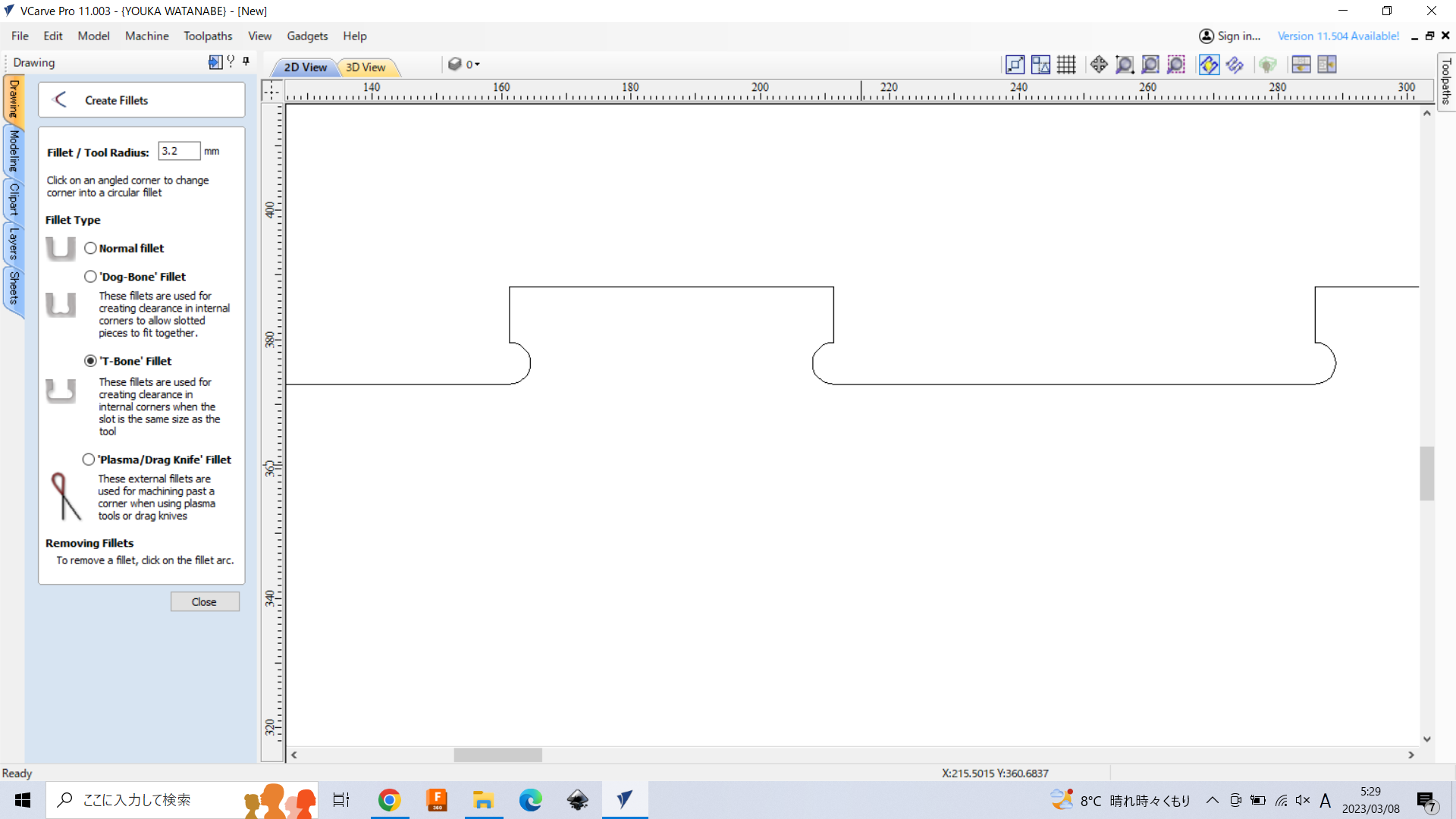
Here added T-bones to all rectunglar notches in the objects.
3. Make Toolpath#
After drawing, setup the toolpath. Click “toolpathes” panel on the right side.
Material Setup#
Z1 Clearance 近すぎると素材のゆがみによってツールの先端が材料にあたってしまうため、余裕をもって15-20㎜程度で設定
2D toolpath#
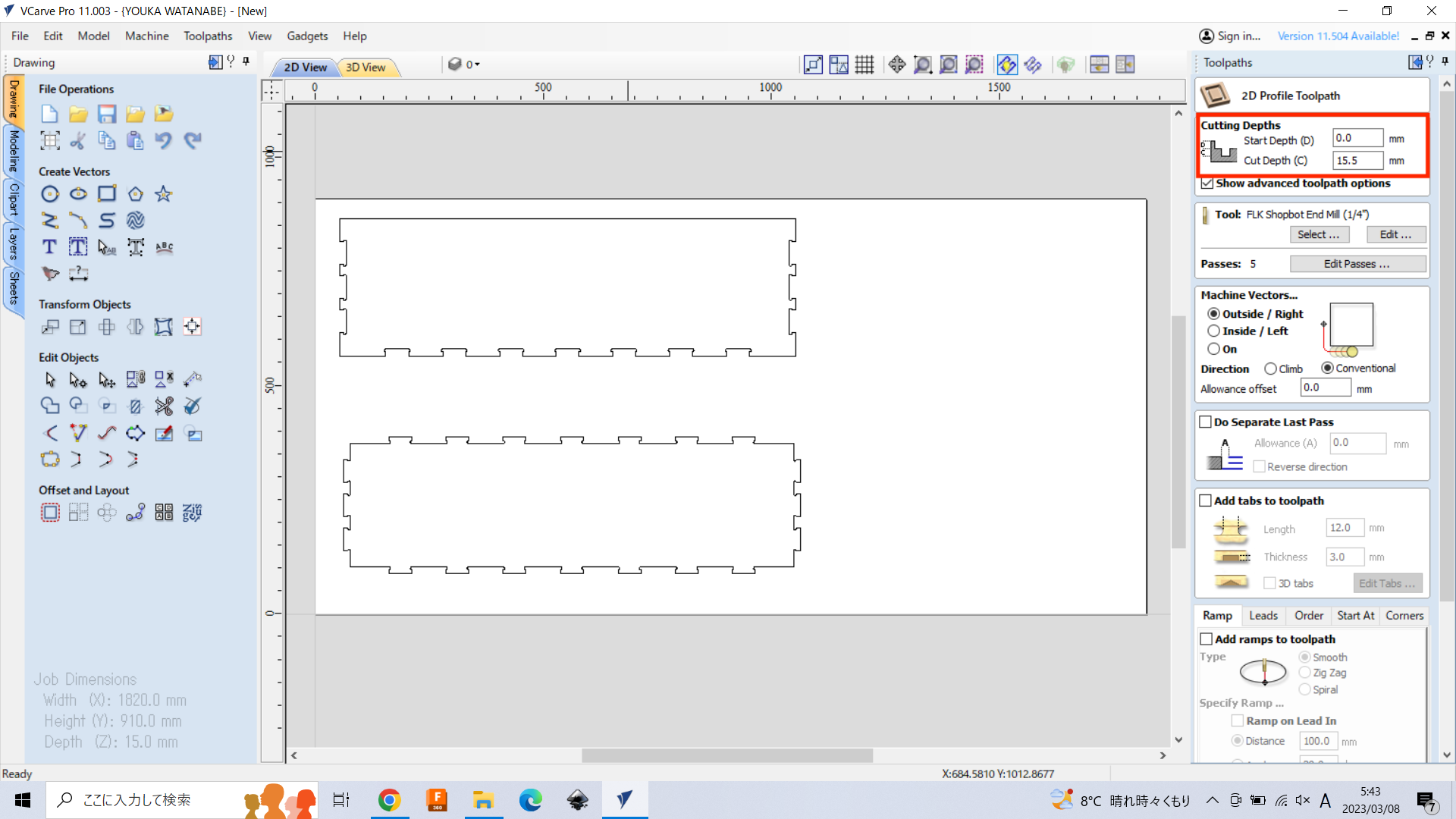
To make a toolpath for cutting the object, click “Profile toolpath”.
“cut depth” is usually the same with the material thickness. However, if you want to cut off the object, it should be add +~0.3-0.5mm. Here, using 15mm material thickness, so cut depth is set as 15.5mm.
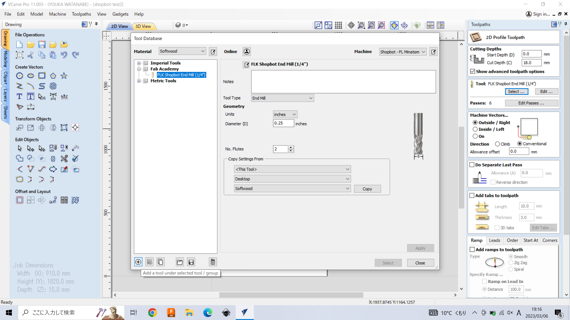
Next is to setup the tool. Click “select” of Tool section. And, you can find the following view. Click “Add a tool” button left below.
*Notice: You don’t need to setup the tool here for the session of Computer-Controlled Machining at Minatomirai (Instructors have already set up).
※Material: 今回の場合はSoftwood。Materialの選択自体は、各素材ごとの設定を呼び出しやすくするためのものであるため、自分が分かりやすいように任意に設定して問題ない。
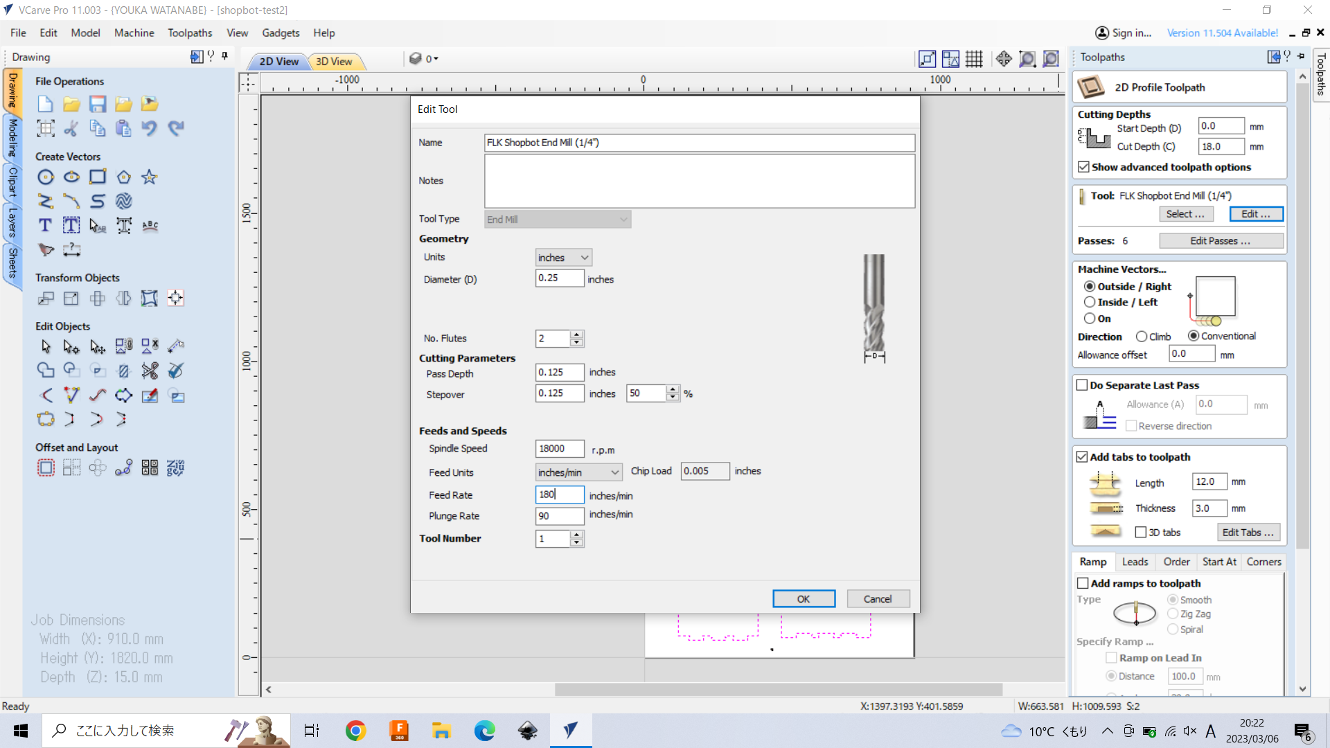
Setup the tool parameter. Checking the basic feathre of the endmill in Fab Lab Kamakura, put appropriate parameters into each items.
- Diameter: 0.25 inch
- No. Fultes: 2
- Pass Depth: 0.125 inch (Default)
- Step over: 0.1 inch (40%: Default)
- Spindle speed: 18000 rpm (maximum size should be the limitation of the machine rpm).
- Feed Rate : 75 mm/sec
- Plung Rate: 30 mm/sec (a half of feed rate)
- Chip Load: 0.0005 inches (rpm / feed rate)
| Item | Contents |
|---|---|
| Pass Depth | 一回でどれだけ切り込むか。 最大値は直径だが、実際はその半分程度に設定するのが適切。 3.175が半径なので0.125(デフォルト値)でOK |
| Stepover | 面切削する際に、次の行への移動で前の行と被る幅の度合い。 ※ポケット加工・3D加工の場合に関係 低いと細かく動く。荒くてよいなら大きくする。3Dの場合は10%が基本、5%程度にすることも |
| Spindle Speed | 18000でよい。機材の対応のSpindle Speedにもよるため要確認 ※スピンドルにスペックが書いてある。カットするのみであれば早い方が良い。穴をあける場合は回転数遅い方が良い |
| Feed Unit | mm/sec |
| Feed Rate | 素材による。合板であれば 70-75。広葉樹だと50程度 |
| Plunge Rare | Feed Rateの半分 |
Machine Vectors… choose Outside / Right. Direction shoukld chose “conventional”.
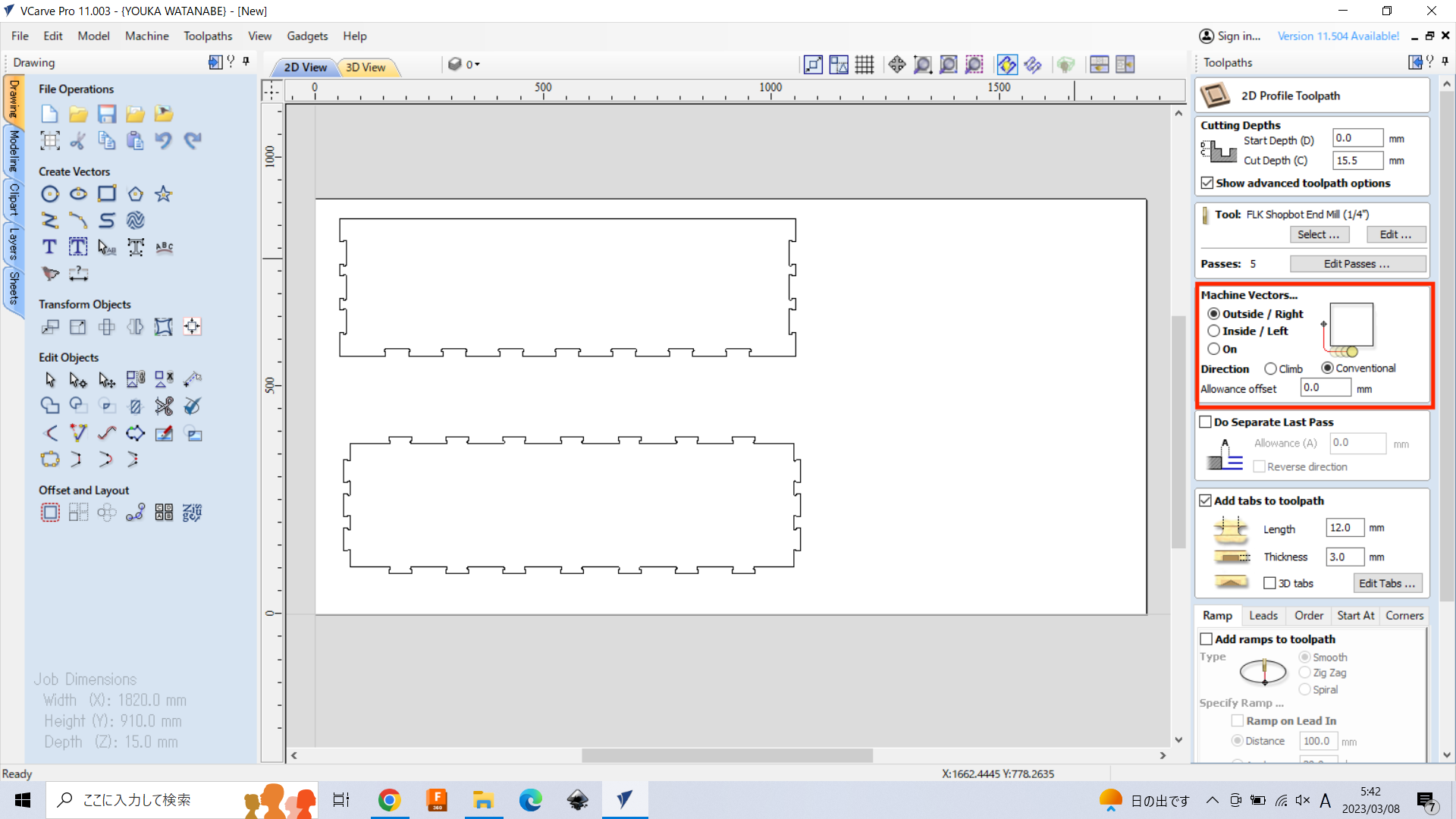
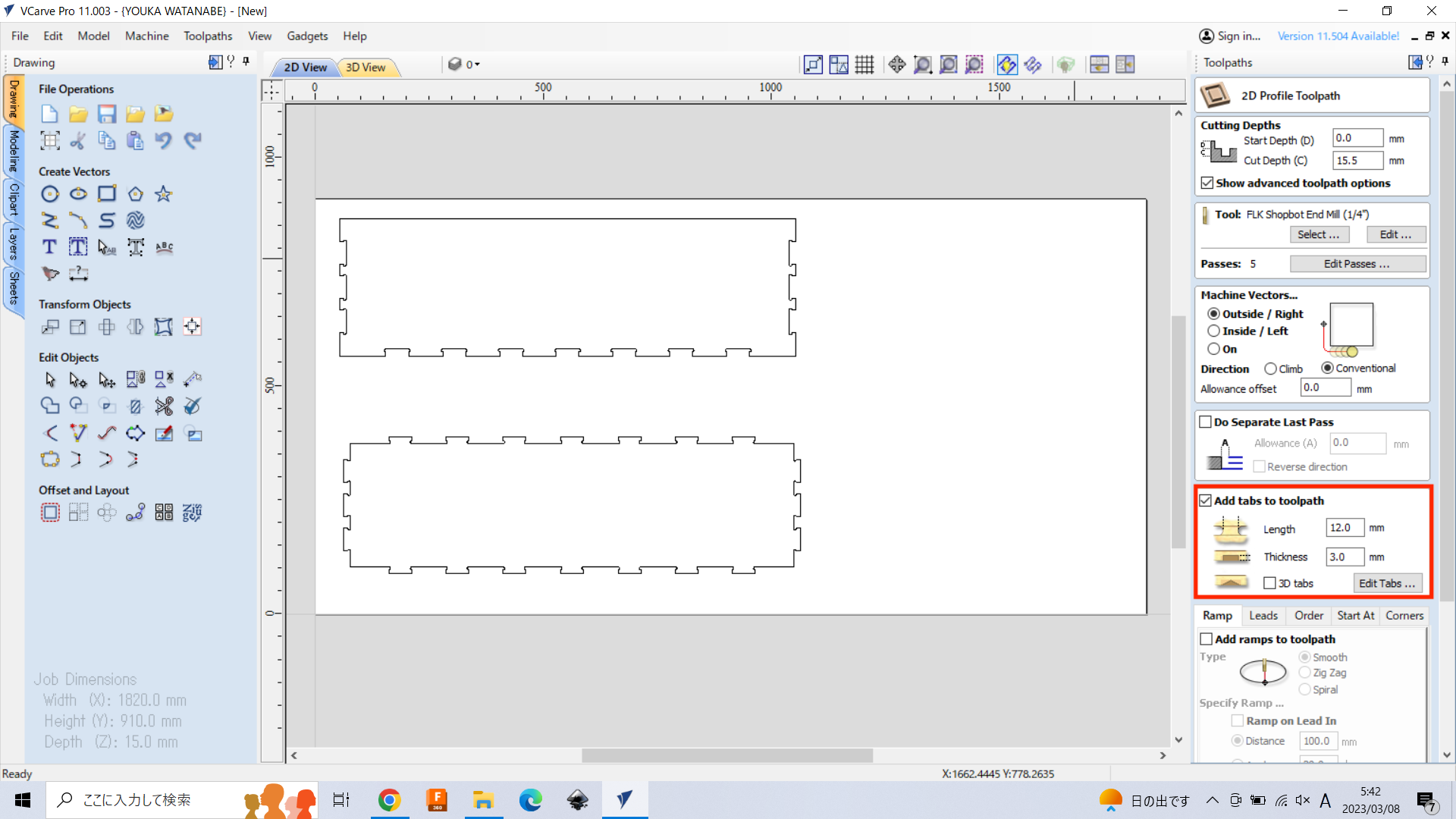
Add Tabs: the most important part in generating toolpath.
Check “Add tabs to toolpath”, then input the appropriate parameter. ※手で切る場合は薄めに設定
- Length: input the length of tab. Generally 10~12mm
- Thickness: input the thickness of the tab. Generally 3~5mm.
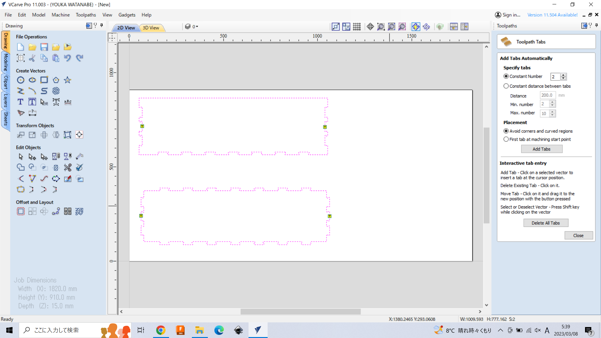
Then, click “Edit tabs”
Add tabs to the objects. Usually, tab sould be added as following the same direction to the grain of wood.
Then, “calculate” button on the bottom.
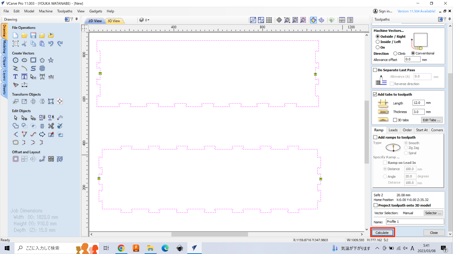
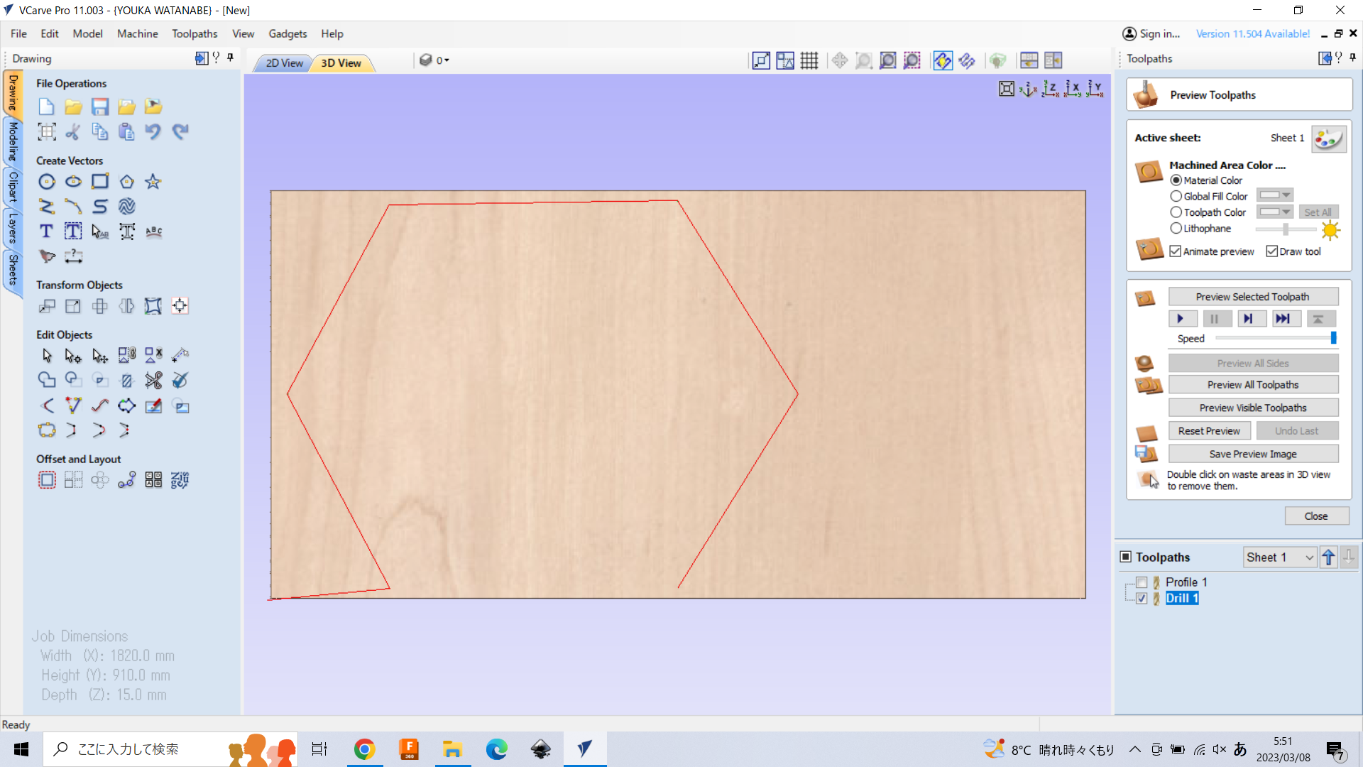
Then, you can preview the toolpath on 3D View.
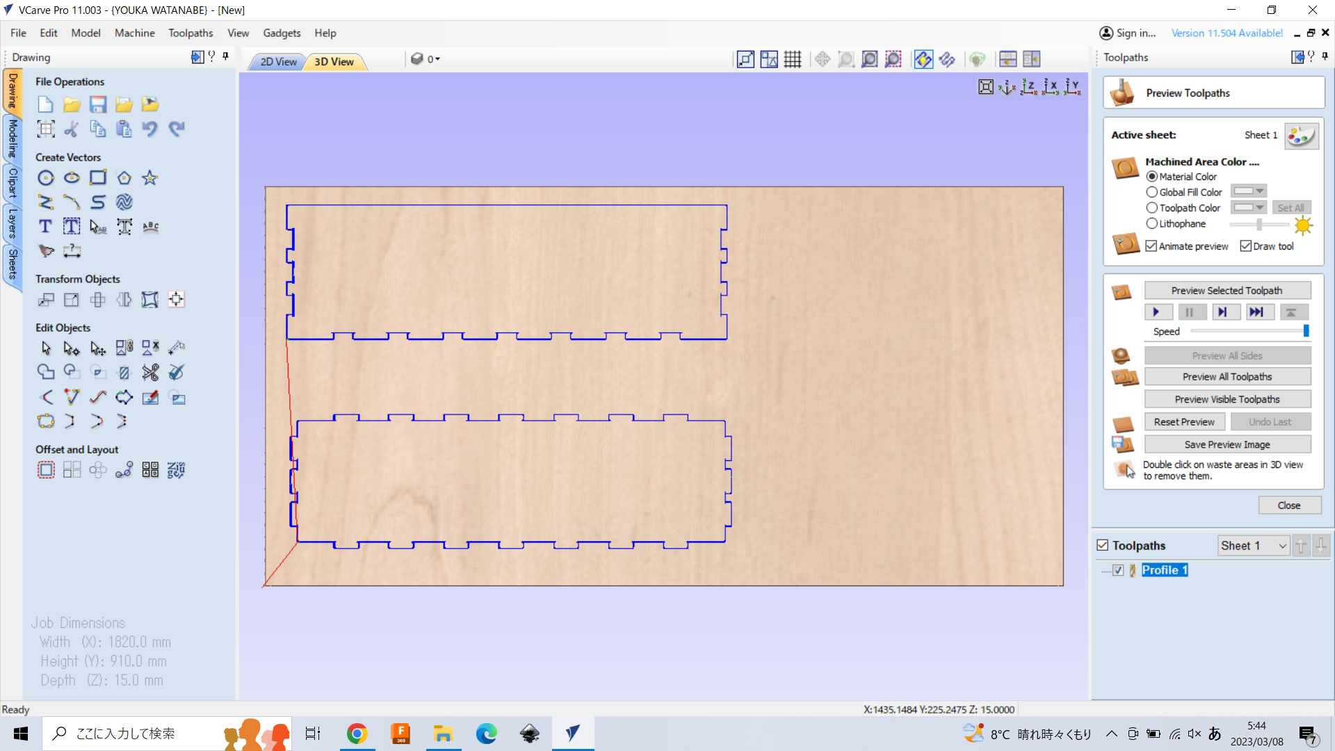
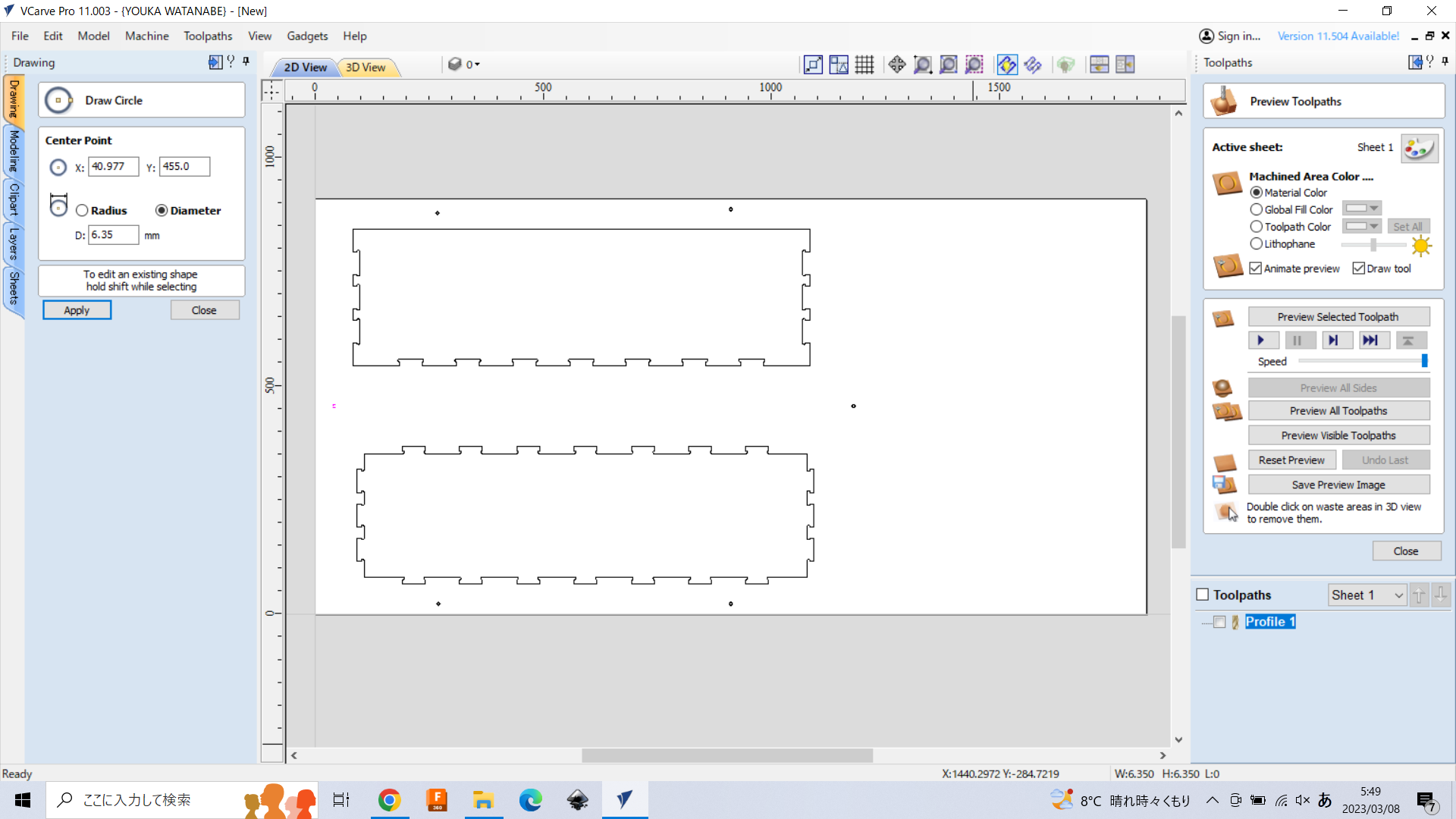
4. Add Marks for Screw#
Also, it is better to add the Marks to put screw using “Draw Circle”. Check the “radius” and the size should be set as the same with the radius of endmill you will use. Here, we will use Lab’s endmill, so we put “3.2” mm (or 3.175mm, 0.125inch = 3.175mm).
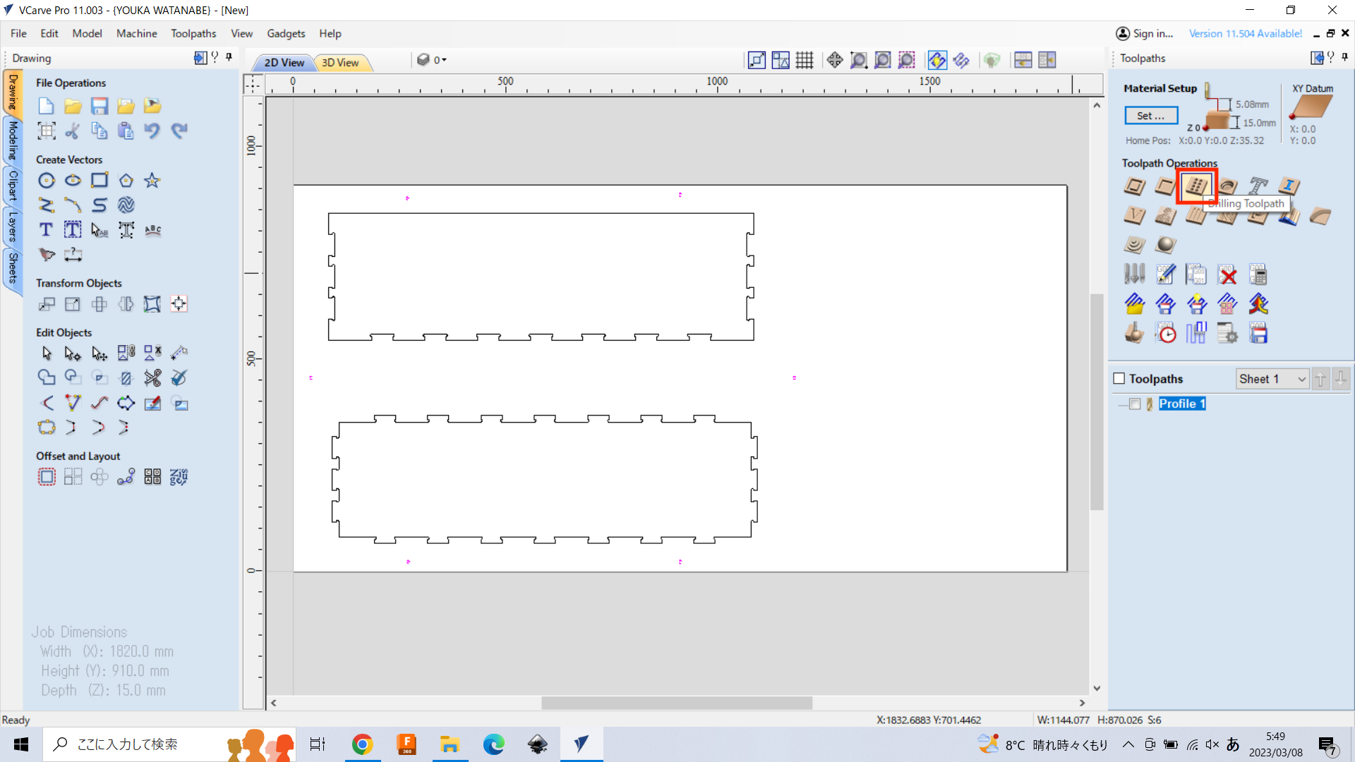
Select “Drill toolpath” on the toolpath tab.
Set the “cut depth” as 0.1 mm. And, select the same tool with preview path. You don’t need to change other config parameters.
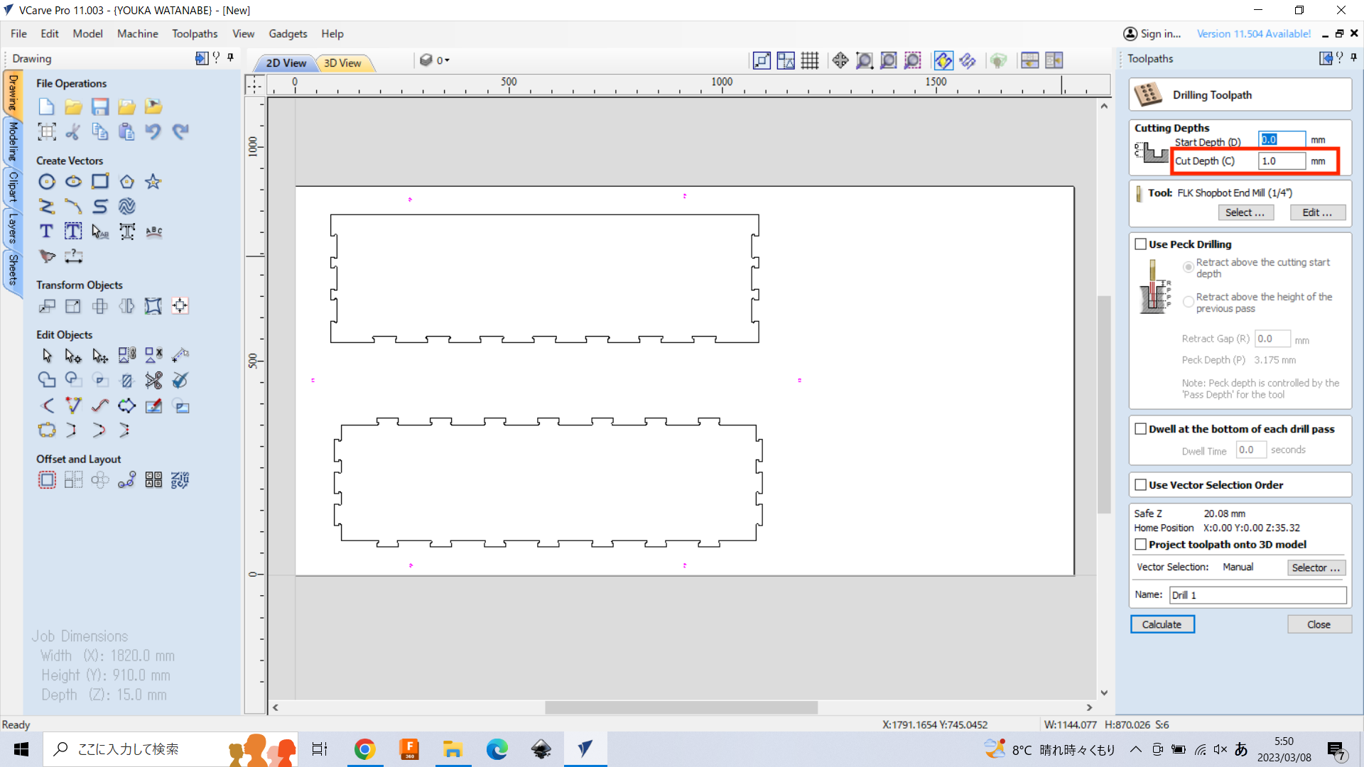
Then, push “calculate” on the bottom, and you can see the toolpath on 3D View.
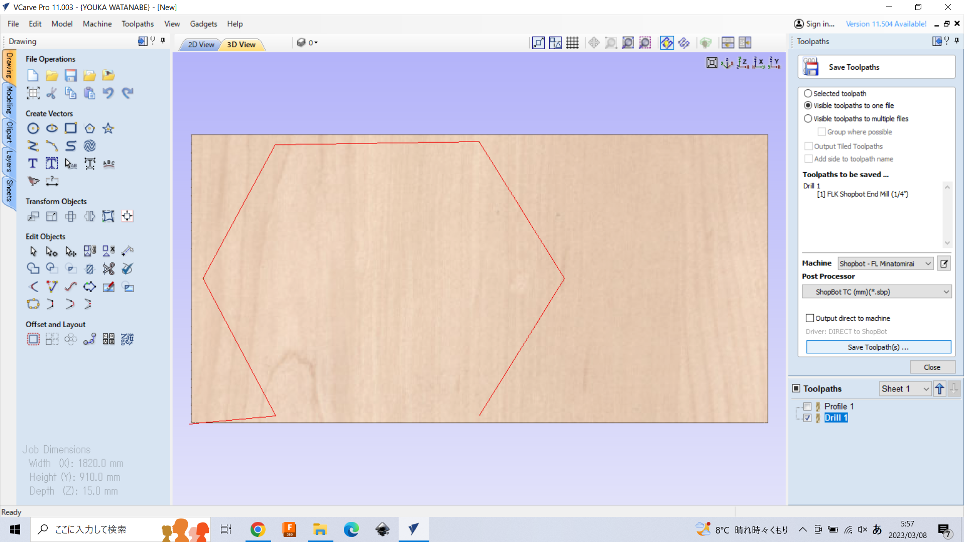
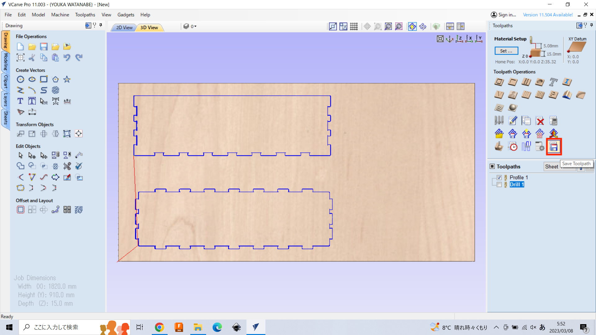
5. Save Toolpath#
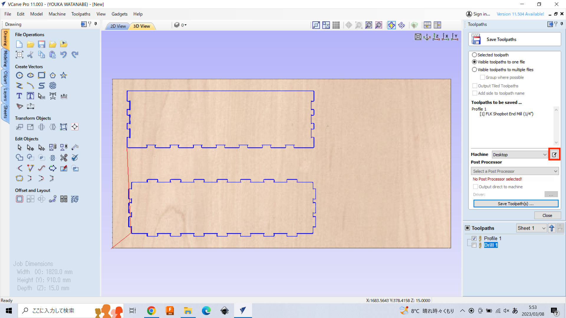
To save the toolpath, select the toolpath and push “save toopath”.
If the machine configuration for Shopbot does not installed, it have to be downloaded. Push “Machine Configuration Management” button.
*Note: For Computer-Controlled Machining session, you don’t need to do this task (instructors have already installed).
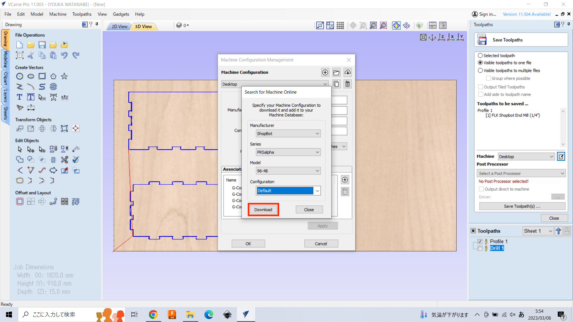
Push “Search Online for your machine” button to search and download maciine configuration.
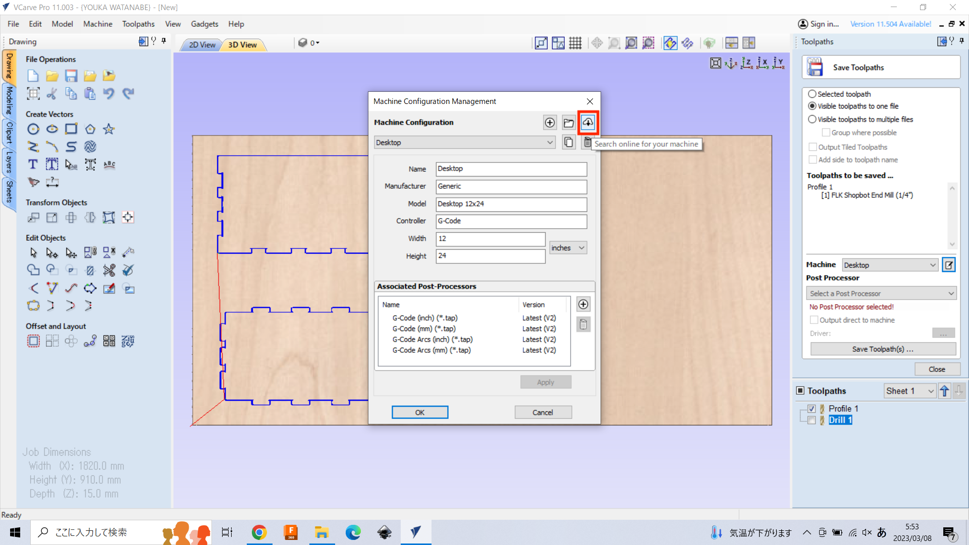
Search the Fab Lab Minatomirai’s Shopbot type: “SHOPBOT PRS Standard 96-48”. You can find as the following and push “download”. ここでは、Assosiated PostProcessorで適切なポストプロセッサを選ぶのが重要! 今回の場合は、Shopbot TC (mm)(*sbp)を設定する事。
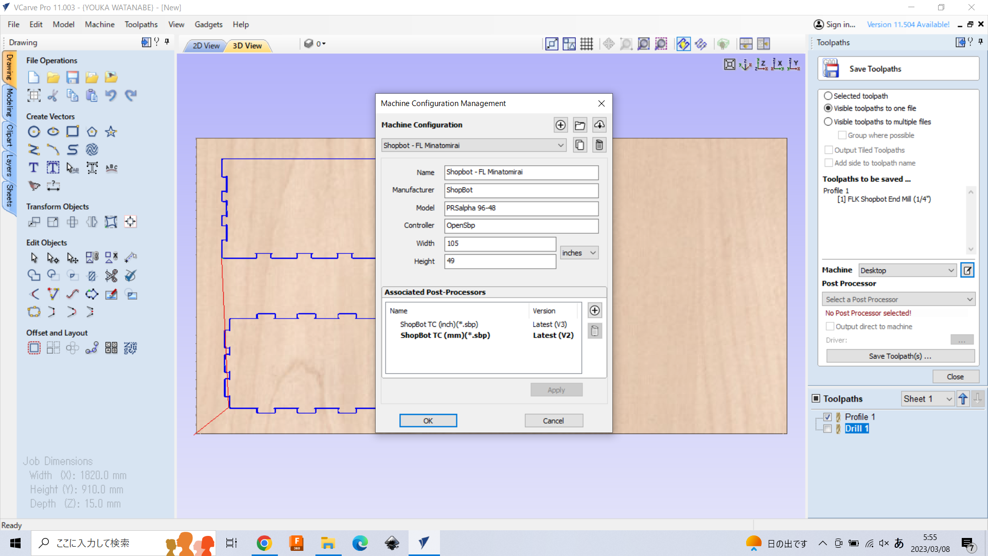
Then, you can preset the machine configuration for Fab Lab Minatomirai. Add Name of machine configuration and push “OK”.
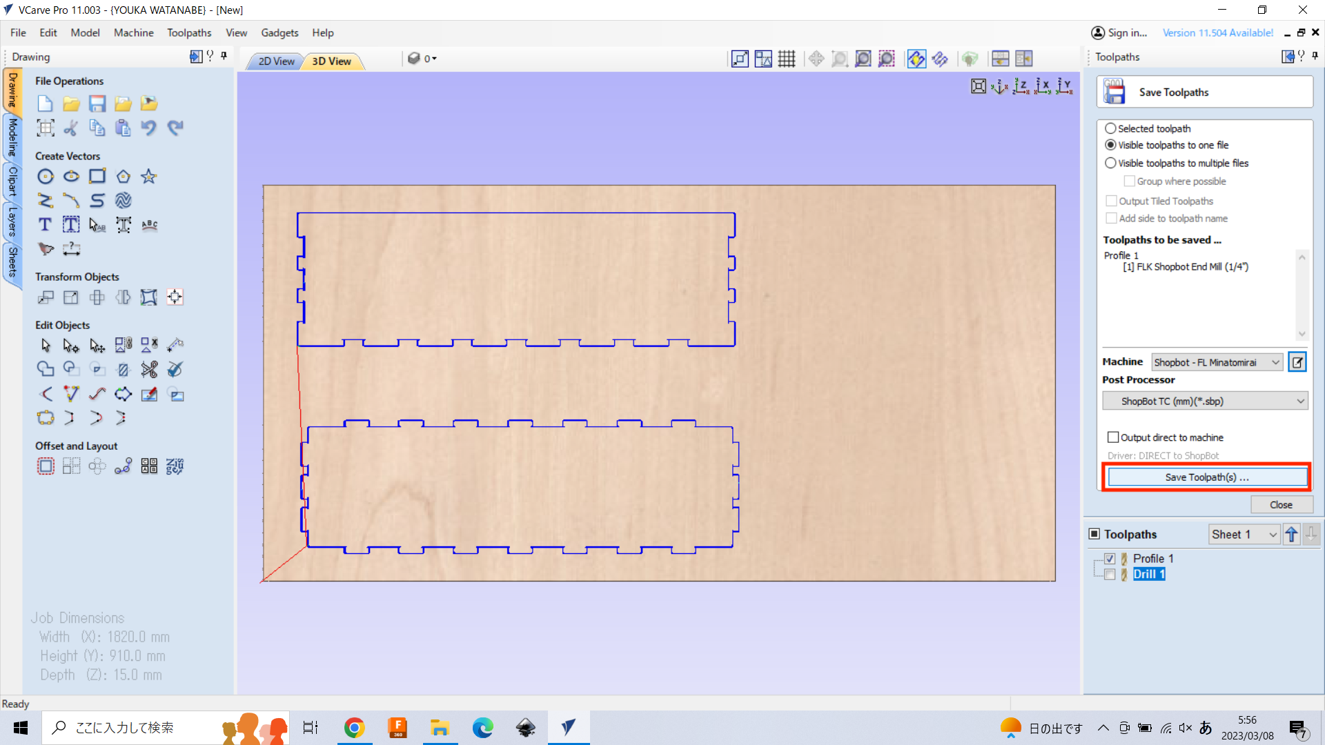
Push “Save toolpath” to save.
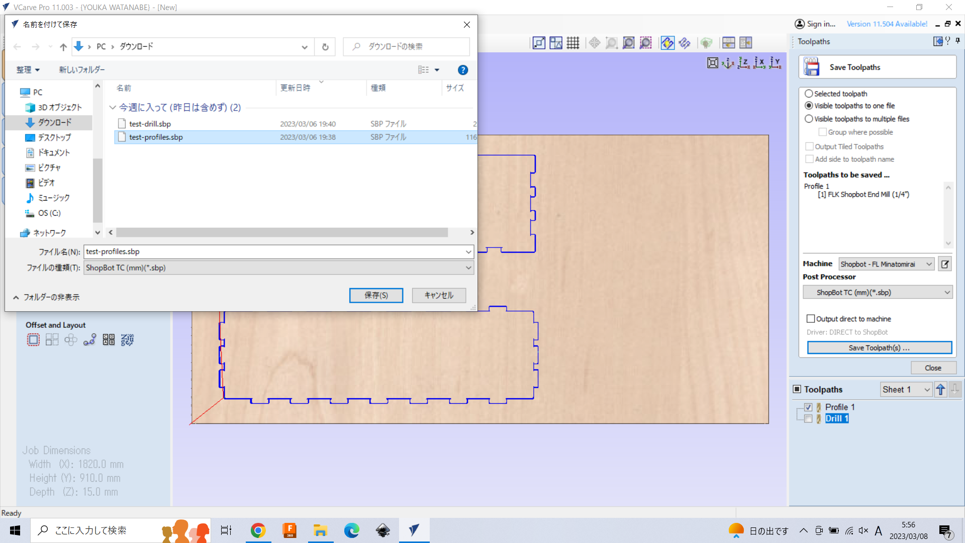
Put the file name and “save”, then, you got the .sbp file.
To save the toolpath for screw, un-check the profile toolpath and check the drill toolpath. Then, push “save toolpath”.