USB-D11C-serial#
Author : Jun Kawahara (FabLab Kamakura)
Date created : 2/16/2022
updated: 2/18/2022 for Windows.
updated: 2/26/2022 corrected on 4k9 ohm resistor
tested environment#
- macOS 10.15.7 Catalina
- Windows 10 using Parallels Desktop 17 for Mac
install edbg#
edbg “is a simple command line utility for programming ARM-based MCUs through CMSIS-DAP SWD interface. It works on Linux, Mac OS X and Windows.“
Download an edbg binary for your OS.
For Mac user, make PATH to a downloaded folder. In .bashrc or .bash_profile, add a path to your edbg folder, like,
export PATH=$HOME/(your directory)/edbg:$PATH
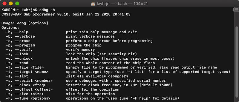
Then, try edbg -h command to see if the command works. If it works, it will return messages like this.
For Windows users, the command should be like edbg-windows-r29.exe -h
My misunderstanding on 4k9 resistor#
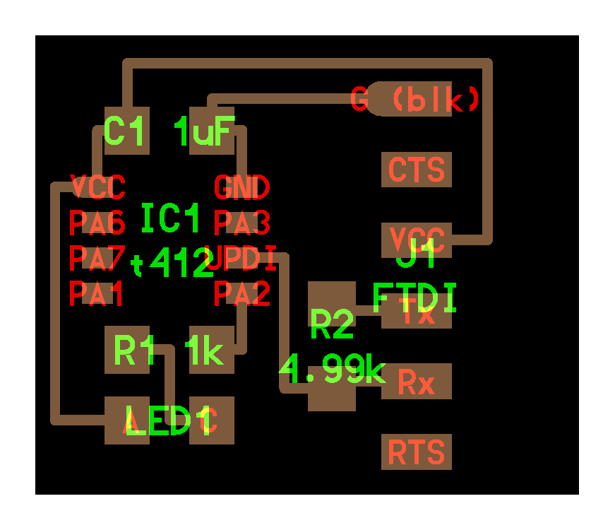
A UPDI programmer is very simple, a TX, RX, and a suitable resistor. Connect TX from the PC UART to a 4K7 resistor. The other side of the resistor is connected to the PC RX and to the UPDI pin of the processor as shown in the image below.
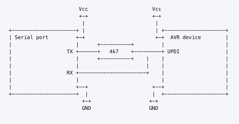
(image source: mraardvark/pyupdi)
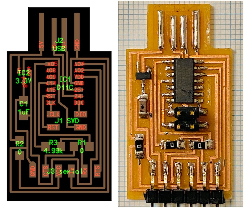
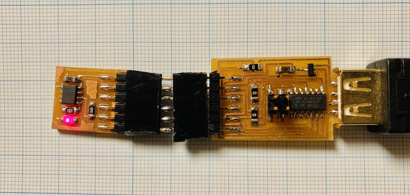
In the image below, I replaced 4k9 resistor with 0 ohm. I thought it was a resistor on TX-UPDI track, but if you look into closely, it is on RX track. I was totally wrong.
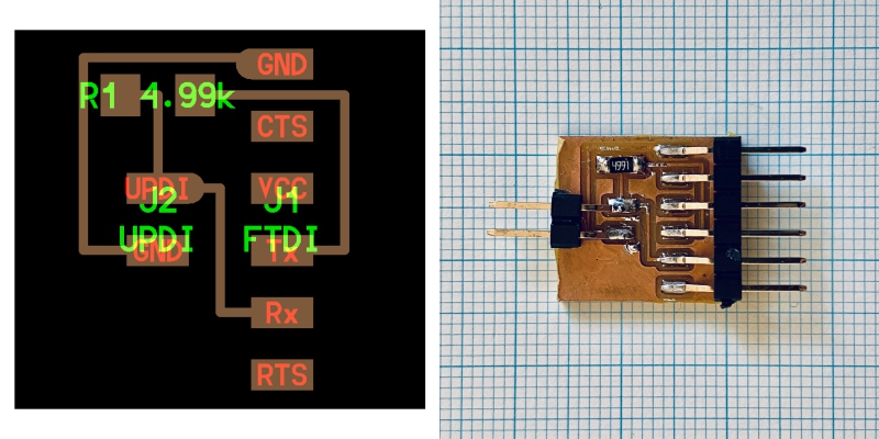
In programming via UPDI with USB-D11C-serial, you also need a serial-UPDI converter.
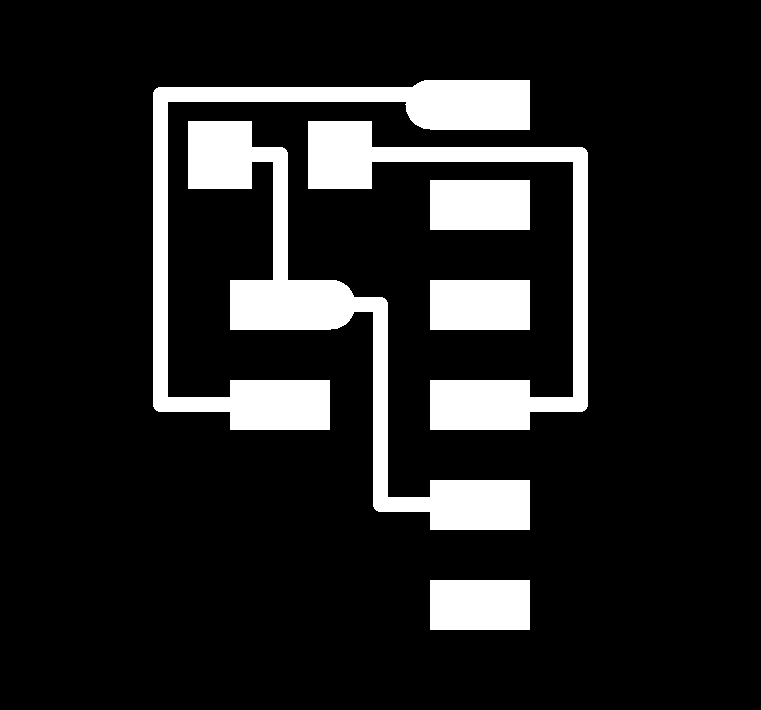
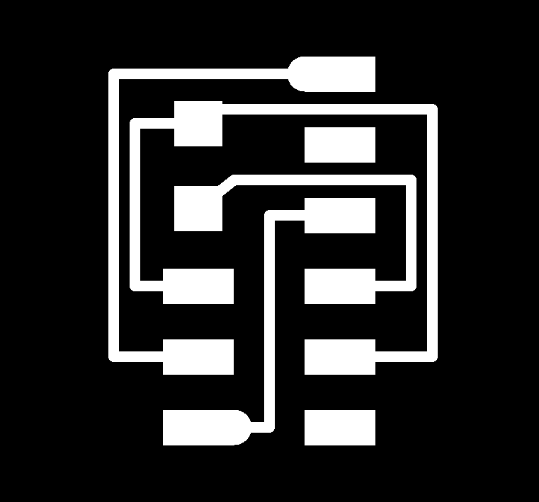
- hello.serial-UPDI board: traces, interior
- hello.serial-UPDI.3 board: traces, interior
burning a bootloader#
Burning a bootloader enables your board to work with an Arduino sketch.
Download a bootloader, sam_ba_Generic_D11C14A_SAMD11C14A.bin.
For Windows, download it to the same folder containing an edbg binary.
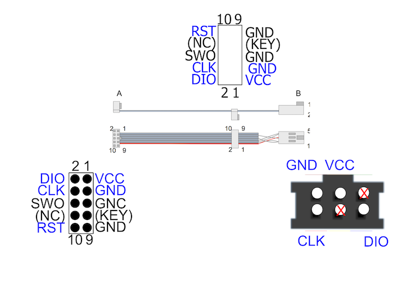
Connect USB-D11C five pins, DIO(2), GND(3), CLK(4), RST(10) and VCC(1), and Atmel-ICE via a squid cable. Refer to the pin mapping table below. Windows installs a driver automatically when Atmel-ICE connected.
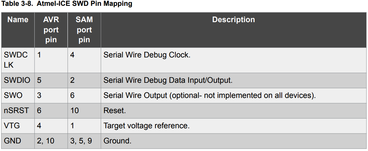 (image source: Atmel-ICE User Guide)
Remember to connect VCC pin like this.
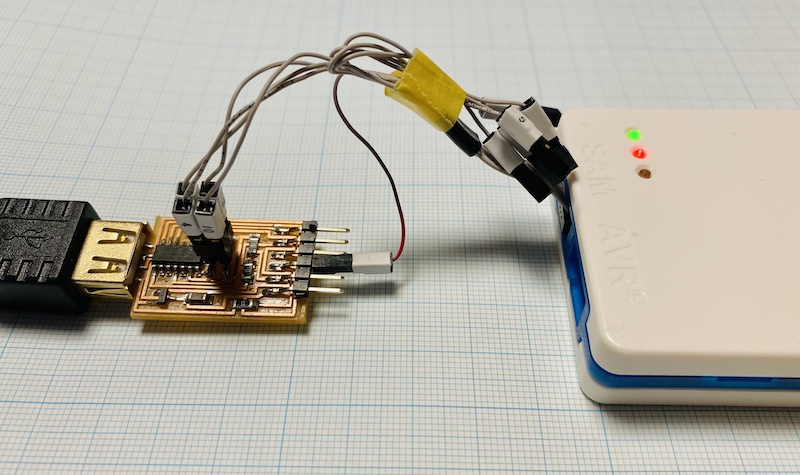
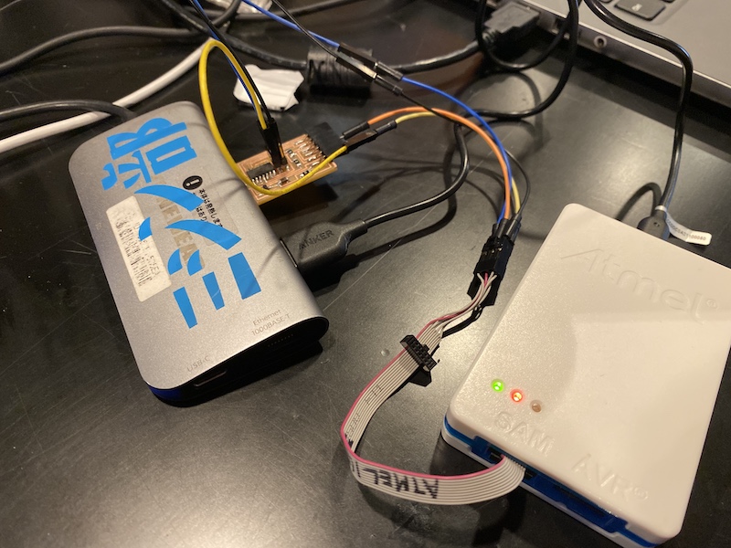
If you don’t have a squid cable, use 100-mil 6-pin AVR ISP cable. Somehow, I could burn a bootloader without RST pin, still I don’t know why.
It’s messy wirings, but trust me, it’ll work.
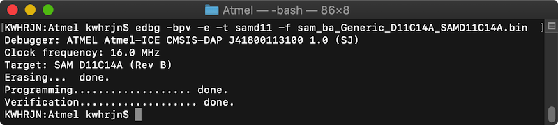
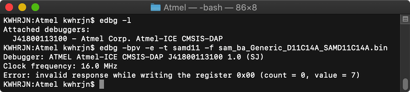
Open terminal and go to Atmel folder. Type,
edbg -bpv -e -t samd11 -f sam_ba_Generic_D11C14A_SAMD11C14A.bin
edbg-windows-r29.exe -bpv -e -t samd11 -f sam_ba_Generic_D11C14A_SAMD11C14A.bin
I hope you get the message like below.
Try lsusb command to see if your PC recognize the board as a USB device.
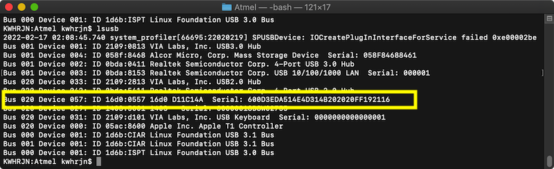
If you got an error like this, check and recheck your connections are right.
install core#
Before uploading an Arduino sketch to your D11C board, you have to install board package, so-called, core, for ATSAMD11C.
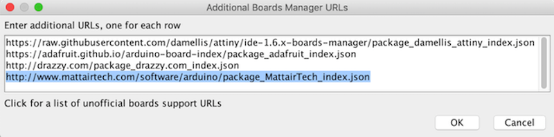
Open Arduino > preferences… Add following URL to Additional Boards Manager URLs section.
http://www.mattairtech.com/software/arduino/package_MattairTech_index.json
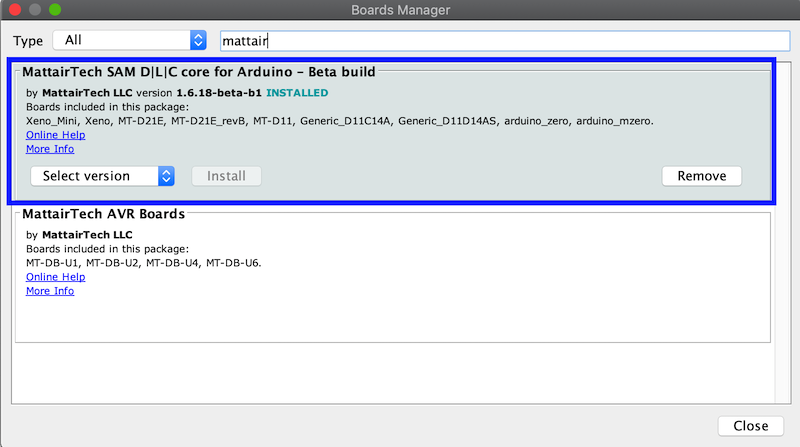
Go Tools > Board > Board Mangers…, search mattair and install MattaireTech SAM D|L|C core for Arduino.
upload a sketch#
Download a sketch, SAMD11C_serial.ino , and open it with Arduino IDE.
Go Tools > Board. Select Board, Microcontrollers, and others as an image shown below. Then, upload the sketch.
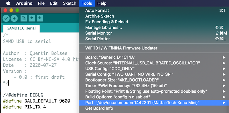
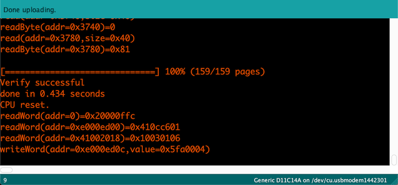
If you got “done uploading” message, the board now will works as USB-serial bridge.
programming example#
install megaTinyCore#
I use a hello.t412.blink board as a UPDI programming target. Before programming a tinyavr, you have to install a core for tinyavr.
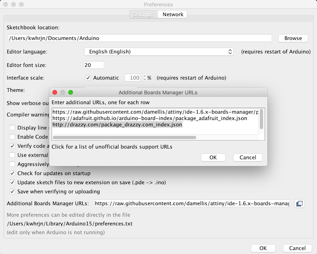
Launch Arduino IDE, open Arduino > preferences…, Add following URL to Additional Boards Manager URLs section.
http://drazzy.com/package_drazzy.com_index.json
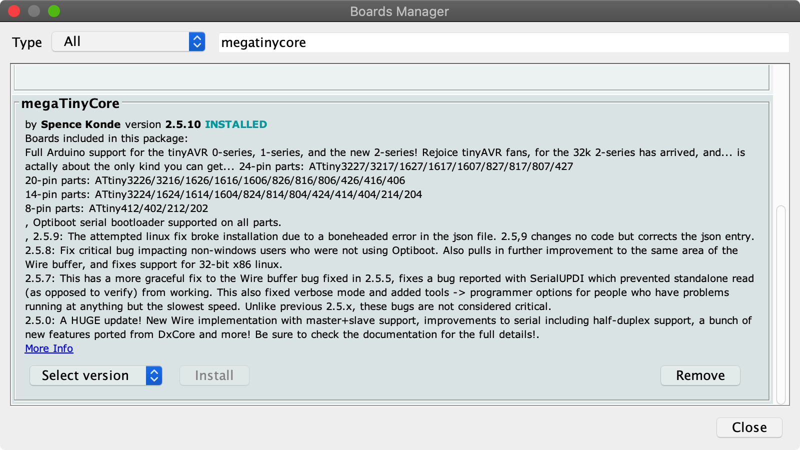
go Tools > Board > Board Mangers…, search megatinycore and install its latest version. 2.5.10 is the latest version as of Feb 2022.
Now you are ready for programming tinyAVRs!
ATtiny412#
blink
I assume that you already have made a hello.t412.blink.
download hello.t412.blink.ino, open it with Arduino IDE.
connect your computer, USB-D11C-serial, and hello.t412.blink board
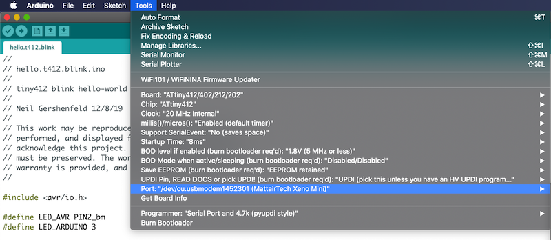
Inside Tools menu, select Board, Chip, Port and other options. Also remember to select a Programmer: “Serial Port and 4.7k (pyupid style)” or SerialUPDI - SLOW 57600 baud, any platform, any voltage, any adapter.
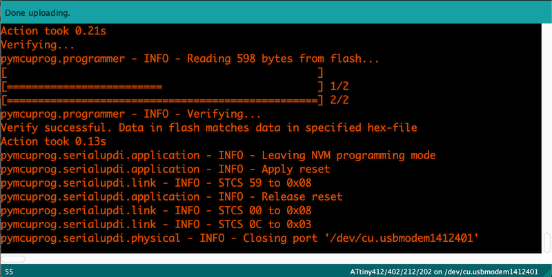
Then, upload your sketch. After long long verbose, you ill get Done uploading message on your window. An led on your board must be blinking now.
Congratulations!!!!
references#
- Electronics Production - Fab Academy 2022
- Embedded Programming - Fab Academy 2022
- edbg - ataradov/github
- SAMD11C14 UART/UPDI programmer - Fab Academy Quentin Bolsee
- SAMD11C_serial - qbolsee/github
- Atmel-42330C-Atmel-ICE_User Guide-10/2016 - Microchip