Simple Core XY Pen Plotter#
Author : Yosuke Tsuchiya (FabLab Kamakura)
Date created : 12/31/2020
Last Modified: 01/01/2021
This is a documentation about how to make a simple Core XY Pen Plotter. As a sample to study about Core XY (and what you need to do in MTM assignments), you can use it.
シンプルなCore XY機構のお絵描きマシーン作り方をドキュメントします。MTM課題に向けて比較的簡単なCore XY機構の学習や、マシン制作でどういった動作が求められるかを把握するなどに役立ててください。
Bill of Materials (用意する物)#
This simple Core XY Pen Plotter need the following materials. You can buy most of mechanical parts at Amazon, Monotaro. You can also buy Electronics Parts at Digi-ke and some Japanese local shops such as Akizuki Denshi (Japan) or Switch Science. But, I also recommend you to check your lab’s inventory if some materials are there.
このページで紹介するシンプルお絵描きマシンの作成には、以下の素材が必要です。メカニカルパーツの多くは、Amazon, モノタロウなどで購入できます。電子部品はDigi-Key のほか、秋月電子、スイッチサイエンスなどで購入できます。ただ、ラボで制作する際はいくつかの部品はラボにあるかもしれませんので、あわせてラボのインベントリーリストを確認することをお勧めします。
Mechanical Parts(メカニカルパーツ)#
| Name | Size | Required Number | Link |
|---|---|---|---|
| liner Bushing Straight | inside radius: 8mm, size: 24mm | 6 | monotaro |
| Half Screw with Hexagon Hole | size: M5, Screw Length: 22mm, Total Length: 35mm | 8 | monotaro |
| Hexagon Nut | size: M5, Screw Pitch: 0.8mm | 8 | monotaro |
| C Shaft SN | size: 8mm (radius), length: 250mm | 4 | monotaro |
| Timing Belt | width:6mm, length: 5m | 1 | Amazon.co.jp |
| Timing Belt Pully | inside hole radius: 5mm, outer radius: 16mm | 10 | Amazon.co.jp |
Electronics Parts(エレクトロニクスパーツ)#
| Name | Required Number | Link |
|---|---|---|
| Arduino UNO | 1 | Switch Science |
| CNC Shield v3 | 1 | Amazon |
| NEMA Stepper Motor (bipola) (17 stepping) | 2 | Amazon |
| Stepper Motor Driver (A4988 or DRV8825)) | 2 | Amazon |
| micro servo SG-90 | 1 | Amazon |
| Bread Board | 1 (2 is better) | Amazon |
| Bread Board Jumper Wire Set | 1 | Amazon |
| Jumper Wire (male-to-male) | as many as | Switch Science |
| 100 uF Electrolytic Condenser | 1 | Akizuki Denshi |
| Regulated Power Supply | 1 | Amazon |
About Core XY#
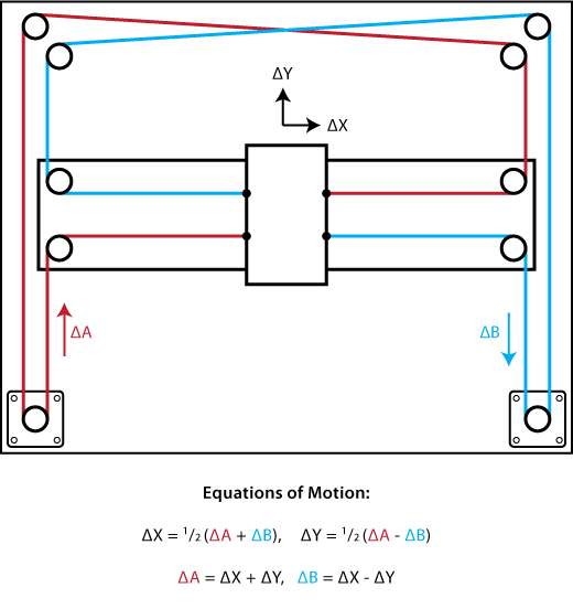
Core XY is a mechanism that moves End Effectors (Pen, Laser, 3D Print Extruders) on X and Y axes with two stepper motor as following:
Core XY は、以下の図のように 2つのステッピングモーターを使ってエンドエフェクター(ペンとかレーザーヘッドとか3Dプリンタの樹脂射出口とか)をX軸・Y軸方向に動かすメカニズムです。
 Quote: corexy.com
Those work as follow:
- When two stepper motors rotate same direction, the end-effector move to X axis.
- When two stepper motors rotate opposite direction, the end-effector move to Y axis.
- When rotating one stepper motor, the end-effector move diagonally.
Core XYは具体的には以下のようなメカニズムで動きます
- 2つのステッピングモータを同じ向きへ回転させることで、エンドエフェクターはX軸(横)に動く
- 2つのステッピングモータをお互い反対の方向へ回転させることで、エンドエフェクターはY軸(縦)に動く
- どちらかのステピングモーターのみを回転させることで、エンドエフェクターは斜めに動く
Here is a test video of core xy mechanicsm with using moc-up machine. Please also check the following video to confirm above. Generally, before you start to building machine, I will recommend you to check the mechanism with making simple moc-up machine.
以下のビデオは、実際にCore XYのモックアップを段ボール紙を使って制作し、動作を確認したビデオです。こちらをみて、上記のメカニズムを確認してください。実際のマシン制作を行う前に、このビデオのように簡単なモックアップを制作してメカニズムを確認しておくことをお勧めします。
At first glance, Core XY is just a simple mechanism to move End Effector as X and Y axes. But, you can add Z-axes mechanism easily. Actually, it could be used not only 2D machine but also 3D CNC or Printers.
一見すると、CoreXYはエンドエフェクターをX,Y軸に動かす単純なメカニズムのように見えます。ですが、当然ながらZ軸のメカニズムも簡単に加えることができます。実際に、Core XYは2Dのマシン(Cutting, Plotting etc)のみならず、3D CNCやプリンタなどでも採用されています。
Design the machine by CAD#
Design CoreXY Pen Plotter with using your CAD software. Here, I used Autodesk Fusion 360, and show some basic design principle of my Core XY Pen Plotter. You should also check Jun’s documentation about the detaild machine designning by Fusion 360.
CADソフトウェアを使って実際に制作するマシンをデザインしてゆきます。ここでは、Autodesk Fusion 360を使ってのCore XYお絵描きマシンの基本的なデザイン方針を示します。具体的なマシンデザインの手順などは、JunさんのCNCドキュメンテーションなどを参照ください。
#
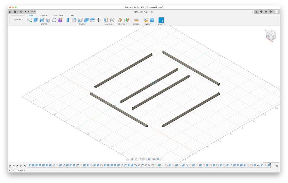
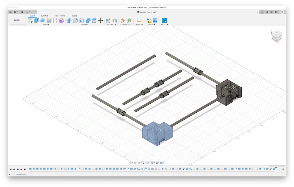
This Core XY Pen Plotter is designed to use 3D printer for making assembling parts. First, we design the base frame (8mm x 250mm C Shaft SN) and deploy them as following.
このCore XY お絵描きマシンは、パーツ部分を3Dプリンタを使って制作するようにデザインします。まず、基本となるフレーム(250mmシャフト)をデザインし、以下のように配置します。
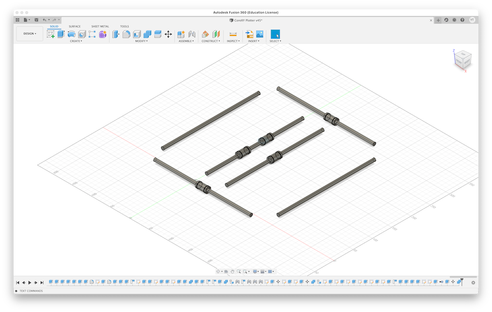
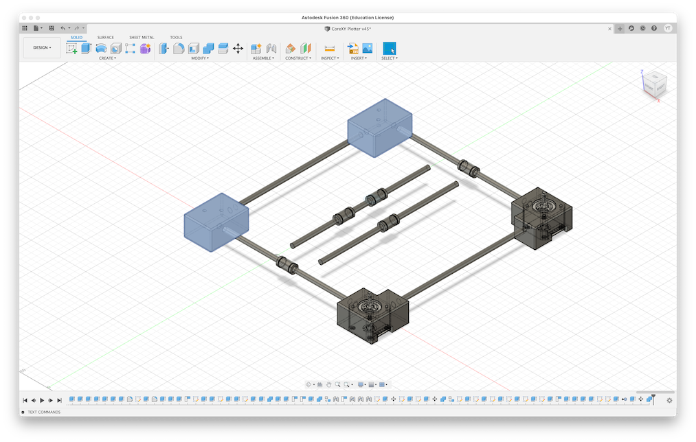
Next, we design liner bushes to use end effector parts and deploy them as following.
次に、エンドエフェクタを移動させるために必要な、リニアブッシュをデザインし、以下のように配置します。
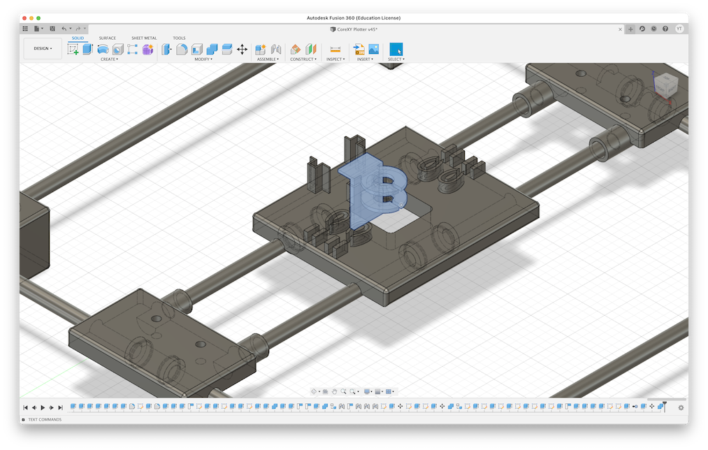
Then, we design the assemble parts. First, we design left bottom and right bottom assemble parts. Those are the places that stepper motors are also deploy. So, we insert the design of stepper motor from [insert] -> [insert a manufacturer part]. After that, we design the assemble parts which meets the following requirements:
- Cast the parts to assemble stepper motor
- make 8mm hole to assemble the shaft.
そして、各シャフトを接合するためのパーツをデザインしてゆきます。まずは、左下と右下のパーツをデザインしますが、ここにはステッパーモーターを配置しますので、ステッパーモーターのデザインを挿入しておきます。そのうえで、
- ステッパーモーターを覆えるように内部をくりぬく
- 2つのシャフトを挿入する直径8mmの穴を作る
以上の要件を満たすデザインを作成します
Next, we design top-left and top-right parts. Don’t forget to make 8mm holes to assemble the shaft. Those parts shoud meets the following requirements:
- make two 8 mm holes to assemble the shaft.
- make two 5 mm holes on top surface to assemble timing belt pullies.
続いて、左上と右上のパーツをデザインします。ここは、
- シャフトを挿入するための8mmの穴を2つ作る
- タイミングベルトプーリーをつなげるための5mmの穴を上部に2つ作成する
以上の要件を満たすパーツを作成します。
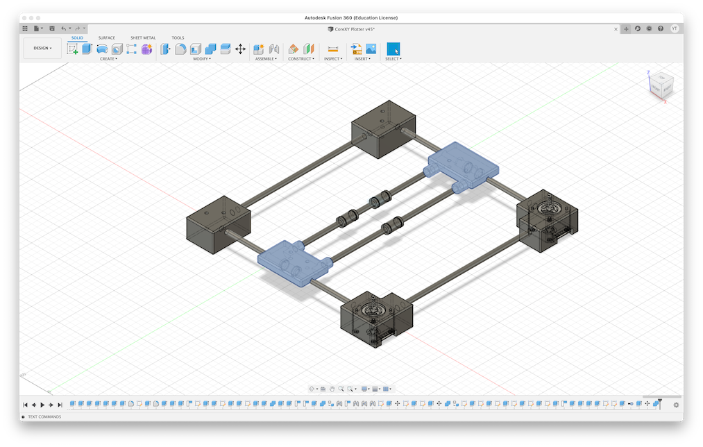
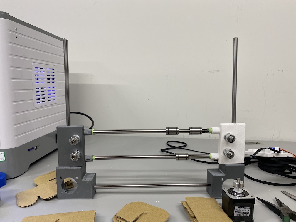
We design the assemble parts of End effector shafts. Those parts should meets the following requirements.
- make two 8mm holes to assemble the shaft
- make a space to assemble liner bush.
エンドエフェクターのシャフトを接合するパーツを作成します。ここも、
- シャフトを挿入するための8mmの穴を2つ作る
- リニアブッシュを接合するためのスペースを作る
以上の要件を満たすパーツを作成します。
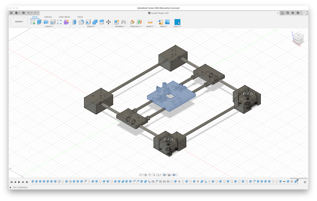
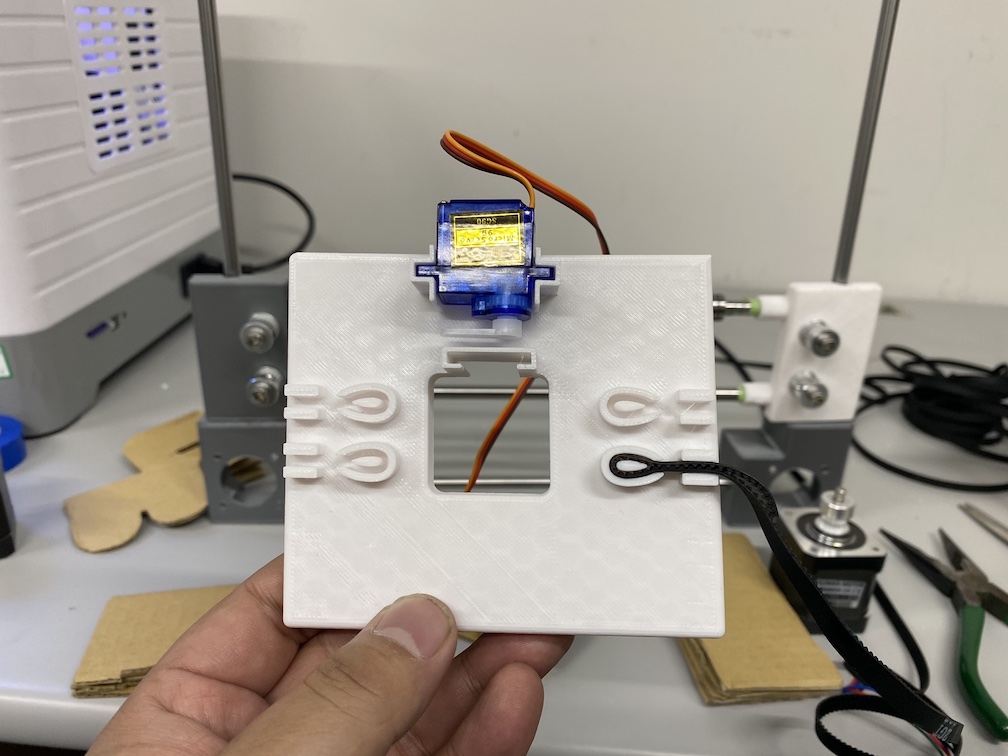
We design the stand of the endeffector. This Pen Plotter use micro servo SG-90 to move pen holder (Up and Down). Moreover, timing belt should be assembled in each four corner of the stand. Therefore, the stand should be designed with meeting the following requirements.
- make assemble parts of timing belt in four corners
- make a part that assemble micro servo
- make a part that assemble pen-holder
- make spaces that assemble liner bushes
エンドエフェクターの台をデザインします。今回のお絵描きマシンは、ペンを上下に動作させる部分でサーボモータ(micro servo SG-90)を使用します。また、タイミングベルトを4隅に接続します。ですので、
- 4隅にタイミングベルトを接続できる部分
- サーボモータを固定する部分
- ペンホルダーを固定する部分
- リニアブッシュを接合するためのスペース
以上の要件を満たすエンドエフェクター台をデザインします。
Finally, we design the pen holder.
最後に、ペンホルダーをデザインします。
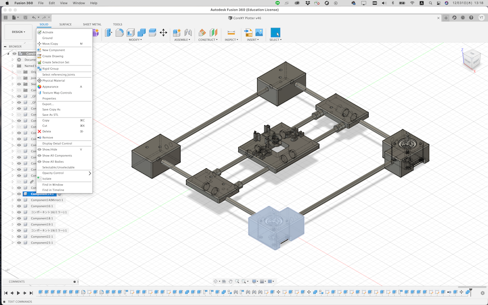
Finally, we finished the design as following.
最終的なマシンのデザインは以下の通りとなります。
You can downlod Autodesk Fusion 360 Archive files (f3z) from here:
Fusion 360上で確認したい場合は、以下のファイルをダウンロードして開いてください。
Fabricate Parts and Building the machine#
We will make assemble parts by 3D Printer. First, we exports each assemble parts as STL file. In Fusion 360, 1) Select a part to export, 2) right click and select “Save as STL”.
マシンの接合部分を3Dプリンタで制作します。まずは、各パーツをSTL形式で書き出します。Fusion 360でSTL形式を書き出すには 1)書き出したいパーツを選択し、2)右クリックで「Save as STL」を選択します。
Next, we will generate G-Code date for 3D printing by slicer software. Also, it is better to check the time for printing. I will use Prusa i3 MK3S, so as as slicer software, I use PrusaSlicer.
次に、3Dプリントするためのデータ(G-Code)を作成します。スライスソフトウェアを使って作成しますので、同時に完成までの時間も確認しておきます。ここでは、Prusa i3 MK3Sを使うので、Prusa Slicerを使用してG-Codeを作成しています。
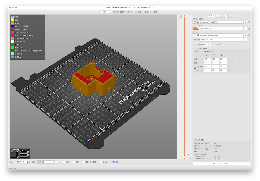
Send this G-Code to 3D printer, and print it!
出来上がったG-Codeを3D Printerへ送り、プリントします。
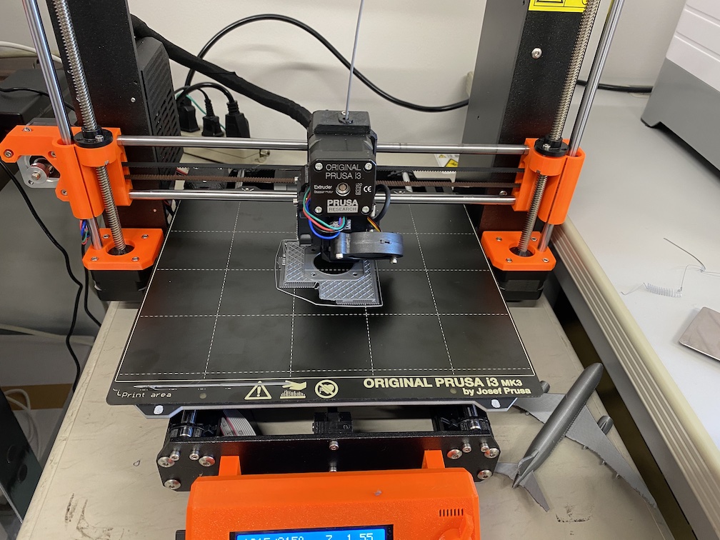
Waiting until all parts are printed out. It takes 3-4 hours in printing each parts and totally 24 hours to finish all parts to print.
パーツが完成するのを待ちます。各パーツのプリントに概ね3-4時間かかるので、全部終わるまで約24時間ほどかかります。
After finishing the print, we will build the machine. Assemble each parts following the above design in Fusion 360.
パーツの3Dプリントが終わったら、マシンを組み立てていきます。Fusion 360 で設計した通りに各パーツを組み立てていきます。
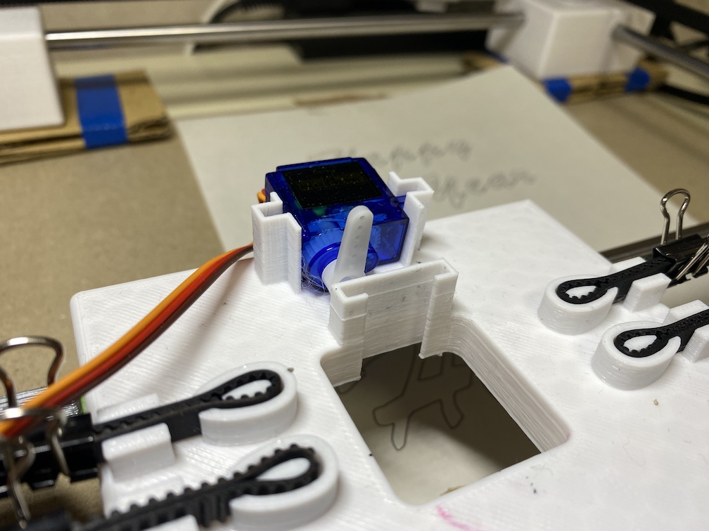
Assemble Micro Servo and Timing Belt to the endeffector stand.
エンドエフェクターの台の部分を組み立て、あわせてタイミングベルトを配置します。
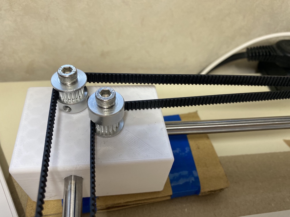
Assembling the timing belt. Timing Belt Pullies should be assembled to each stepper motor. Also, pullies should assemble to the top-left, top-right and each end effector shaft parts with using Half Screw with Hexagon Hole
タイミングベルトを配置します。ステッパーモーターの軸にタイミングベルトプーリーをつけます。また、下図のように左上部、右上部、それぞれのエンドエフェクタのシャフトパーツに六角レンチ穴付きネジを使ってプーリーをを固定します。
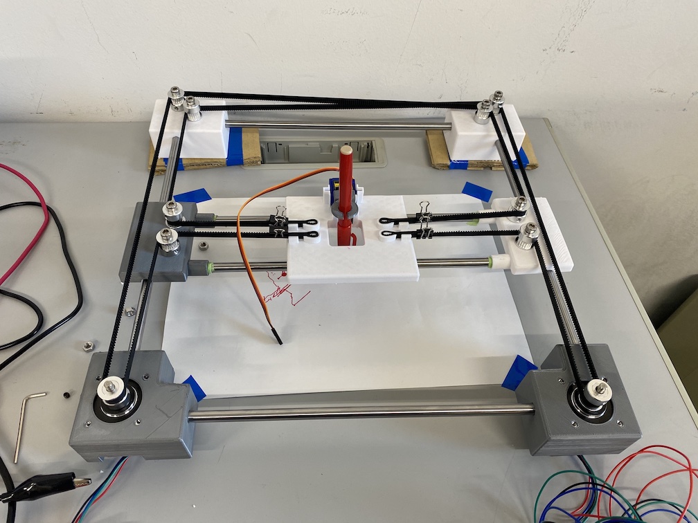
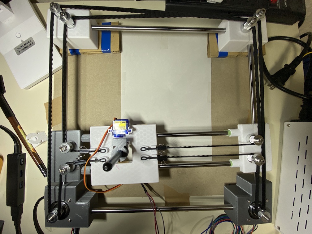
The machine is built as below picture.
完成形は以下のようになります。
Electronics Curcit Design#
Core XY has two stepper motor. To controll each stepper motor from micro-controller board like Arduino UNO, we need stepper motor driver. One stepper motor need one stepper motor driver. Moreover, stepper motor driver need 12v power supply and it cannnot use the micro-controller power supply (5v). We need 12v regulated power supply for them.
Core XY は2つのステッパーモーターで動作します。それぞれのステッパーモータをArduinoなどのマイコンボードから操作するためには、ステッパーモータードライバが必要です。ステッパーモータードライバおよびステッパーモータードライバ自身は12Vの電圧でで動作するので、マイコンからの電源供給では電圧が足りませんので別途12Vの電源を供給する必要があります。
Here is the circuit design pattern of a stepper motor driver. We make this circuit with using jumper wires and breadboard and regulated power supply.
以下が、ステッパーモータードライバDRV8825を用いた電子回路の構成図です。ブレッドボードとジャンパーワイヤ、安定化電源を用いて、2つのステッパーモータードライバを接続する回路を作成します。
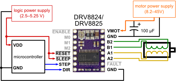
Source:https://www.pololu.com/product/2133
Here is a example of pin assigns of DRV8825 stepper motor driver when using Arduino UNO as micro-controller. Please don’t forget to connect 100 uF Electrolytic Condenser between 12V and GND of regulated power supply.
Arduino UNOをマイコンボードで用いる場合は、以下のような回路構成になります。ステッパーモータードライバ DRV8825の各ピンの接続先は以下のとおりです。安定化電源からの 12V と GNDの間に 100uFの電解コンデンサーを接続することを忘れないでください。
| Pin | Connection |
|---|---|
| VMOT | 12V of Regulated power supply |
| GND | GND of Regulated power supply |
| B2 | Stepper Motor Black wire |
| B1 | Stepper Motor Green Wire |
| A1 | Stepper Motor Red Wire |
| A2 | Stepper Motor Blue Wire |
| FAULT | Not Connect |
| GND | GND of Micro-Controller |
| ENABLE | Not Connected |
| M0 | 5v from micro-controller |
| M1 | 5v from micro-controller |
| M2 | 5v from micro-controller |
| RESET | 5v from micro-controller |
| SLEEP | 5v from micro-controller |
| STEP | Arduino UNO PWM pin (one is to D9, another is to D11) |
| DIR | Arduino UNO PWM pin (one is to D8, another is to D10) |
M0, M1 and M2 pins in DRV8825 are microstep selection pins. For example, we use NEMA 17 200 steps motor and pull-up M1 as High, the step would be 800 and control the positions minutely.
DRV8825ステッパーモータードライバのM0,M1,M2ピンはマイクロステップの解像度を設定するためのものです。このマシンでも使用するNEMA 17 stepモーターは通常は200ステップで1回転しますが、例えばM2ピンをHIGHに設定する(5v電源を接続する)と、800ステップで1回転するようになります。つまり、1ステップごとの回転角度が¼になり、1回転までのステップ数が4倍になるので、その分細かい動作が可能となります。
DRV8825 stepper motor driver has three step size (resolution) select input by Pull-Up/Pull-down each M0, M1, M2 pins. The combination of Pull-Up/Pull-down are here:
DRV8825ステッパーモータードライバは3つのピン(M0,M1,M2)をプルアップもしくはプルダウンすることで、マイクロステップの値を調節します。それぞれのピンをプルアップ/プルダウンする組み合わせによって、以下の表の通りにマイクロステップの値を設定することができます。
| M0 | M1 | M2 | Resolution |
|---|---|---|---|
| Low | Low | Low | Full Step |
| High | Low | Low | Half Step |
| Low | High | Low | ¼ Step |
| High | High | Low | ⅛ Step |
| Low | Low | High | 1/16 Step |
| High | Low | High | 1/32 Step |
| Low | High | High | 1/32 Step |
| High | High | High | 1/32 Step |
When using machine controll, I recommend to pull-up all M0,M1,M2 pins as HIGH, then Microstep resolutin would be 1/32 step.
マシン制御で使用する場合は、1/32 stepに設定する(M0,M1,M2を全てプルアップする)ようにします。上記の回路では、M0, M1, M2 にそれぞれマイクロコントローラからの5vを接続しています。
Test Run: Core XY Arduino Program#
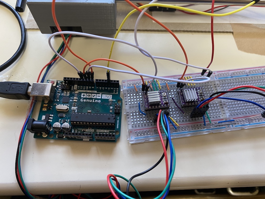
To test Core XY mechanism, you can use Arduino Program donwloded from here. Connect Arduino and the PC via USB cable, download this program and write it into Arduino UNO.
Then, open the serial monitor of Arduino IDE. If you can write the program correctly, you can find the list of command for controlling your Core XY.
Core XY が正しく動作しているか確認するためには、Arduino用のCore XYプログラムを使用します。ここからダウンロードします。Arduino UNOとPCをUSBケーブルで接続し、プログラムをArduino UNOに書き込みます。
そして、Arduino IDEのシリアルモニタを表示します。プログラムが正常に書き込まれていれば、以下の画面のようにコマンドリストが表示されます。
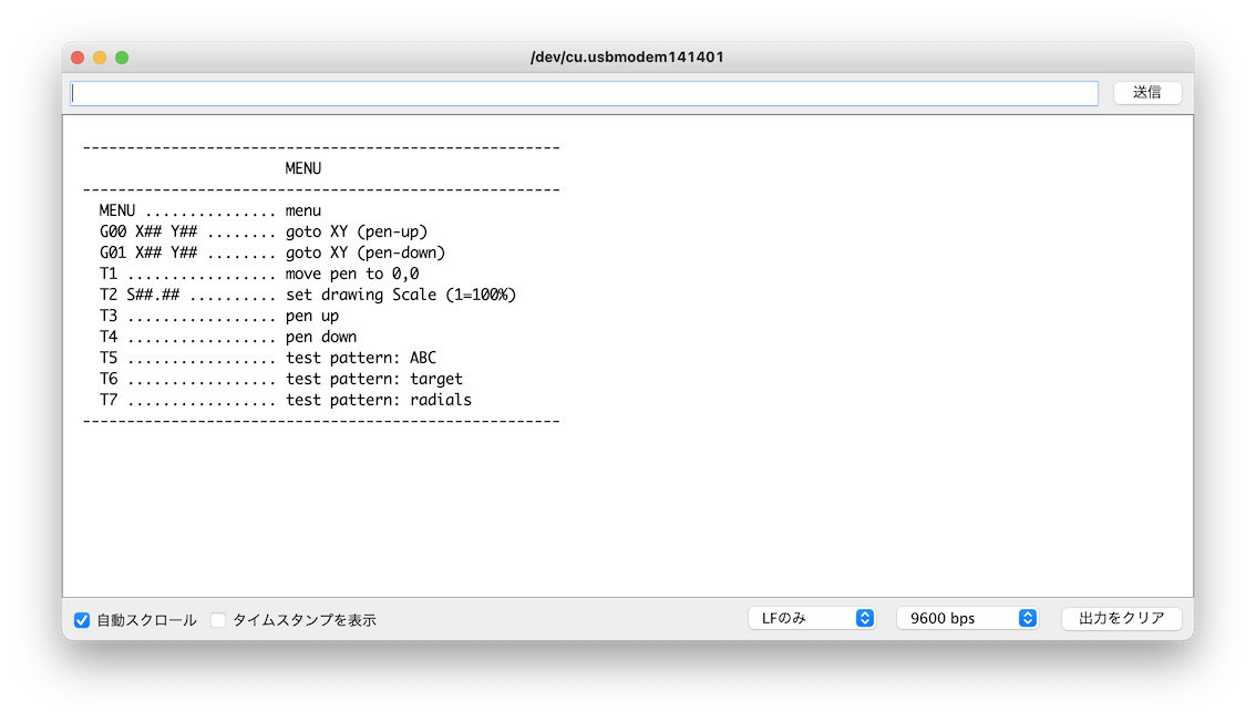
First, Enter “T1” command on serial monitor, and you can see the following command. You can move end effector as following these guideline. Check your machine to work correctly with using it. Type “E” to exit this mode, and type “MENU” and you can see command list again.
まず最初に、Arduinoのシリアルモニタで T1 コマンドを入力しEnterを押します(改行は”LFのみ”に設定しておくこと)。すると、以下の図のようにエンドエフェクタをコントロールするためのコマンドが表示されます。X軸方向には A(左)もしくはS(右)と入力することで1ステップ動作させることができます。Y軸上の場合は K(上)もしくはL(下)です。このコマンドを使って、作成したマシンが意図通りの方向へ動作することを確認してください。終了する場合は “E” と入力します。そして、”MENU”と入力することで、最初のコマンドリストをもう一度表示することができます。
 Next, we check the micro servo condition with using T3 and T4 command, then add an arm to micro servo. Enter T3 command and keep the position of pen-up, then rotate the arm as below picture.
次に、T3, T4コマンドを使ってマイクロサーボが動作していることを確認してください。マイクロサーボが動作していることを確認したら、付属のアームを取り付けます。T3(pen up)コマンドを実行し、ペンが浮いている状態のマイクロサーボの位置に設定し、下図のように上向きにアームを取り付けます。
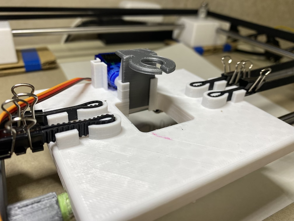
Enter T3 and T4 command, again. Then, check whether the arm rotate up when T3 command are executed, the arm rotate down when T4 command are executed. After that, add pen-holder and try same thing again. Check the pen-holder is up when T3 command are executed, and also check the pen-holder is down when T4 command are executed.
再度 T3, T4コマンドを実行し、pen-upの時にアームが上を向き、pen-downの時にアームが横向きとなることを確認します。Pen holderを取り付けてみて、再度pen-upの時にpen-holderが上がり、pen-downの時にpen-holderが下がることを確認します。
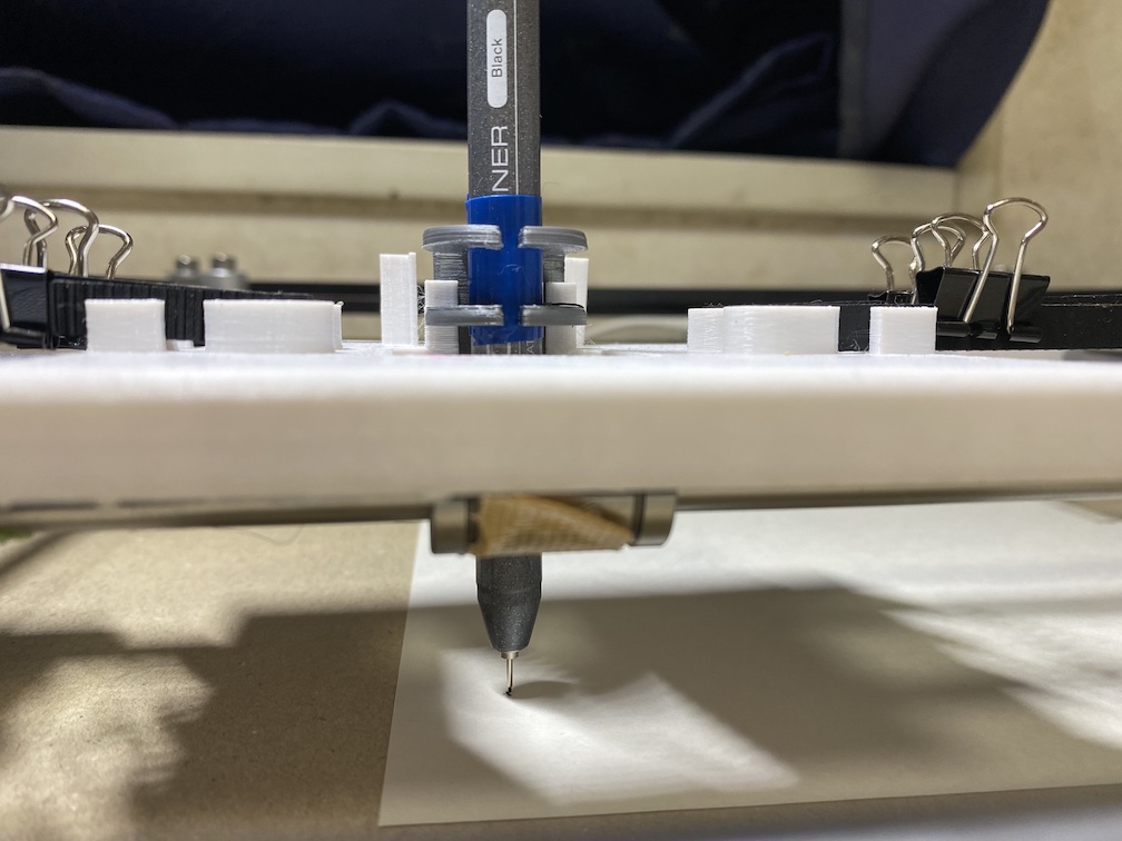
Enter T4 command, and keep the pen-down position. Install the paper for drawing and adjust the height of pen-holder to touch the pen and the paper.
T4コマンドを実行し、pen-down状態にします。お絵描きする紙をセットし、ペンが紙の上に接触する高さでPen-holderにペンを取り付けます。
Move the end effector to origin position with using T1 command, that is near the bottom-left corner. Most of drawing data (G-code) would start from left-bottom origin. Please don’t forget to do T3 command to keep pen-up.
T1コマンドを使ってエンドエフェクターを原点(左下)に移動します。ほとんどのお絵描きデータ(G-Code)は左下を原点として作成されます。実行する際はT3コマンドでpen-upの状態にしてください。
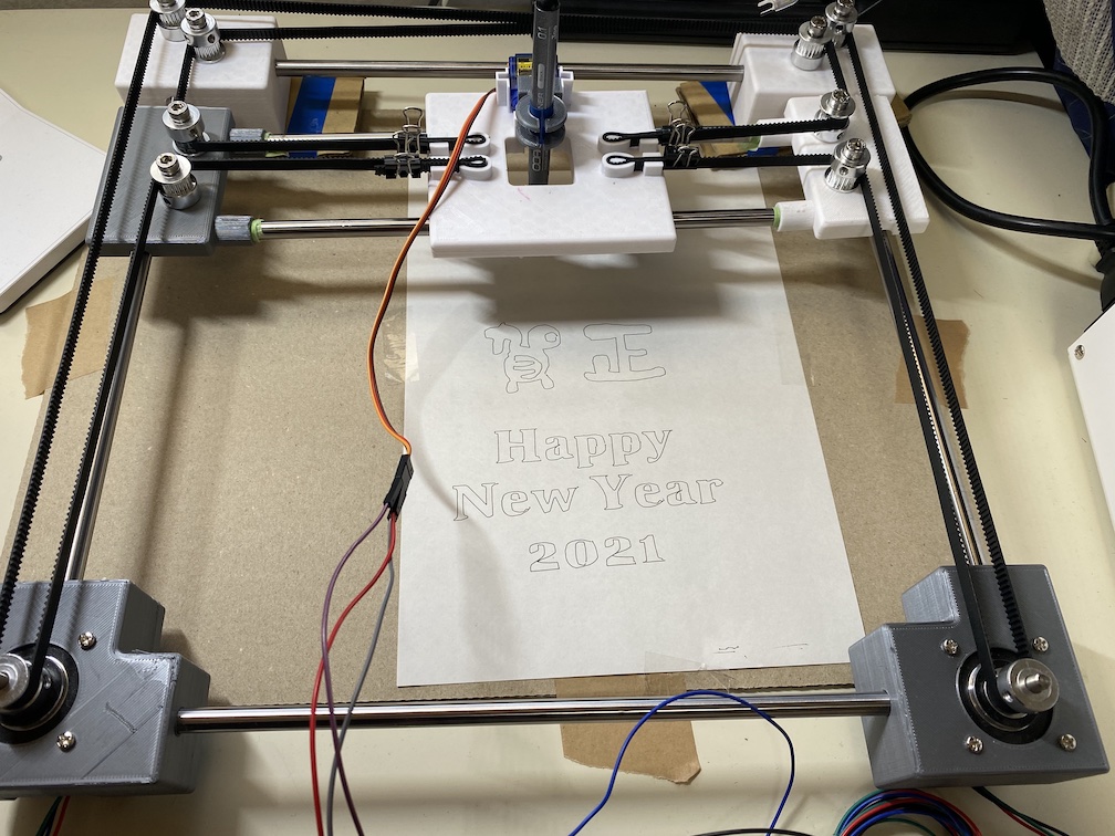
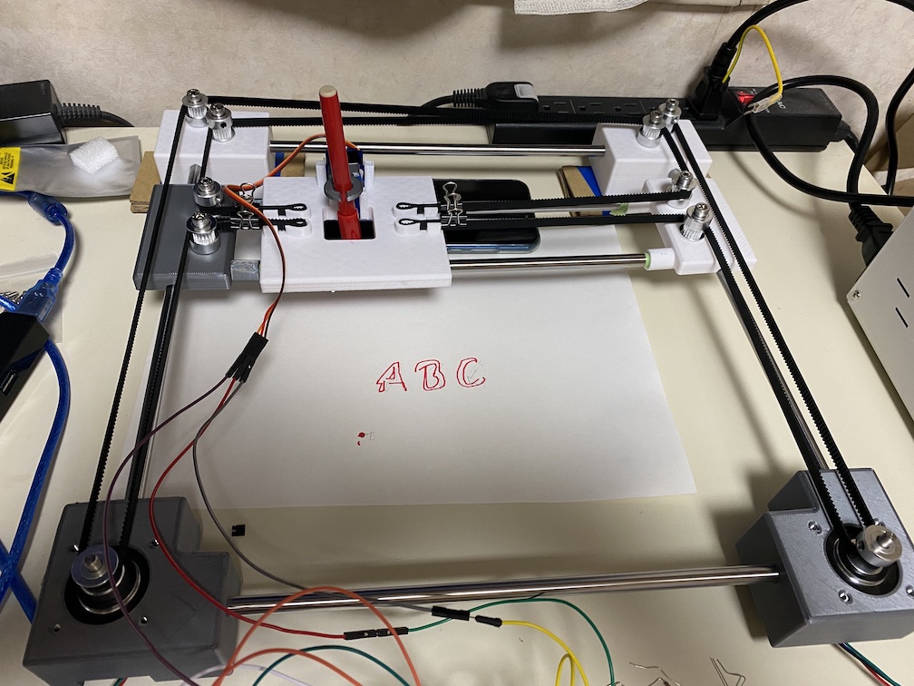
T5, T6 and T7 command are to execute test patter of drawing. Here, we enter T5 command to dreaw the letter A B C. Check the test patter are drawed as following.
T5, T6 もしくはT7コマンドは、実際のドローイングのテストパターンを実行します。ここではT5コマンドを実行してABCの文字を描いてみます。以下のように正常にABCが描かれることを確認します。
Using CNC Shield v3.0#
After confirming the Core XY machine works correctly, we make controller with CNC Shield v3.0. The following is a schematic of CNC shield v3.0.
Core XYが動作することを確認したら、CNC Shield v3.0で制御部分を構築していきます。以下が、CNC Shield 3.0の回路構成図です。

Source: Crazy Engineer’s Drawing Robot Arduino GRBL CoreXY Drawbot
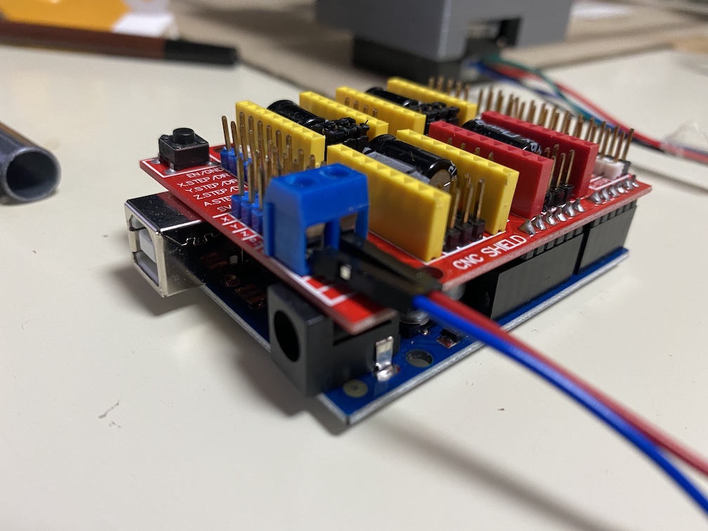
Assemble CNC Shield v3.0 to Arduino UNO as following.
CNC Shield v3.0を以下の通りArduino UNOに接続します。
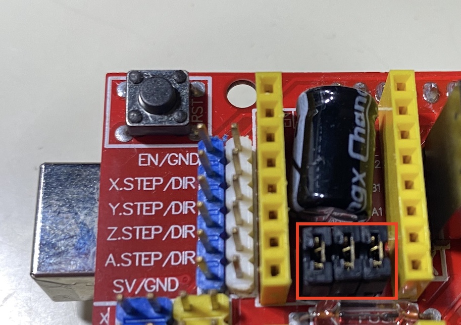
Next, we assemble jumper-pin in each M0, M1, M2 pins located near the place that DRV8255 stepper motor driver should be assembled.
続いて、ステッパーモータードライバを接続する部分のところにあるM0,M1,M2にジャンパーピンを接続します。これによりマイクロステッピングを全てPull-up状態にすることができます。XとYそれぞれのM0,M1,M2ピン全てにジャンパーピンを接続します。
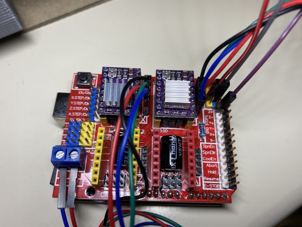
Then, we connect two DRV8825 drivers and two stepper motors. DRV8825 driver connect to a group of 16 (8x2) pin socket which are labeled “X” and “Y”. Be careful to the direction of the driver. The wire from stepper moter should be connected to a group of four pins located near stepper motor driver. In case of a stepper motor in above BOM list, black wire should be located on top. 5v and GND line of micro servo should be connected to the 5v pin and GND pin located right side of the shield. PWM line of micro servo should be connected to Z+ pin located right side of the shield. Finally, DC located left bottom of the shield should be connected to 12v power supply.
DRV8825, ステッパーモーターを以下の通り接続します。DRV8825はシールドのXとYと書かれている差込口のところに接続します。ステッパーモータードライバを取り付ける方向に気をつけるようにしてください。ステッパーモーターのワイヤーは、ドライバの右隣の差込口(4本のピン)に接続します。BOMリストのステッパーモーターの場合は、黒色のワイヤーが上になるように差込ます。マイクロサーボの5VとGNDはシールドの右側にある5VとGNDのピンに接続します。そして、マイクロサーボの信号線はシールド右側のZ+ピンに接続します。左下のDC電源部分のプラスとマイナス部分をそれぞれ12vの電源へ接続します。
Install Grbl Core XY Servo#
The firmware for controlling the machine via CNC sheild v3 should be installed in Arduino UNO. There are a couple of firmwares released as open source, and most popular one is Grbl. However, official Grbl source code doesn’t support Core XY mechanism. So, here, we use “grbl-coreXY-servo” firmware which is adopted to coreXY mechanism with controlling pen-holdor up-down by micor-servo.
CNC Shield を用いたマシン制御のためのFirmwareをArduino UNOにインストールします。オープンソースでいくつか公開されていますが、Grbl などがよく使われています。ただし、公式のGrblはCoreXYへ対応していません。そこで、GrblをCoreXYでのサーボモータでのup-downに対応させた grbl-coreXY-servoを使用します。
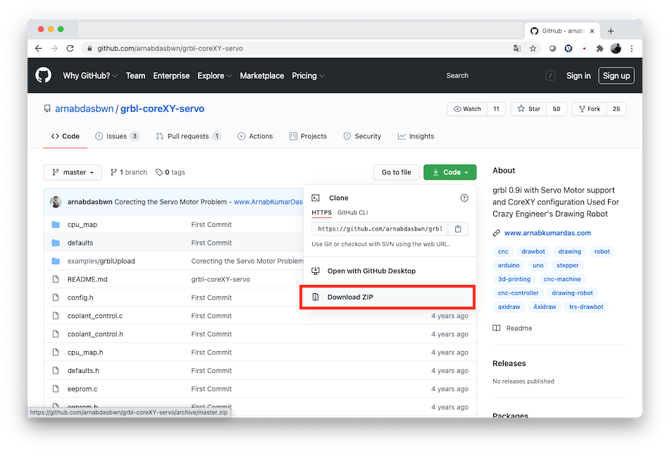
Firest, access to the GitHub of grbl-coreXY-servo, then downlod the zip file of source code of grbl-coreXY-servo.
まずGitHubのgrbl-coreXY-servo のページへアクセスします。ソースコードをzip形式でダウンロードします。
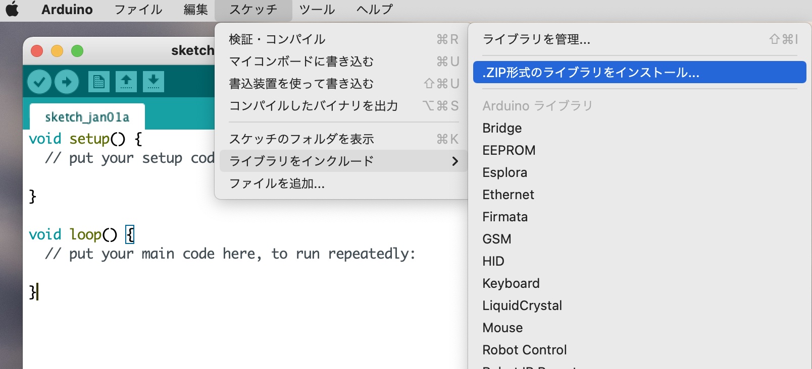
Open Arduino IDE and include downloaded zip file as a library of Arduino. You can do it from: [Sketch]->[include library]->[install .zip file].
続いてArduino IDEを起動して、zipファイルをArduinoのライブラリとしてインストールします。「スケッチ」から「ライブラリをインクルード」→「.ZIP形式のライブラリをインストール」を洗濯します。ダウンロードした「grbl-coreXY-servo-master.zip」を選択します。
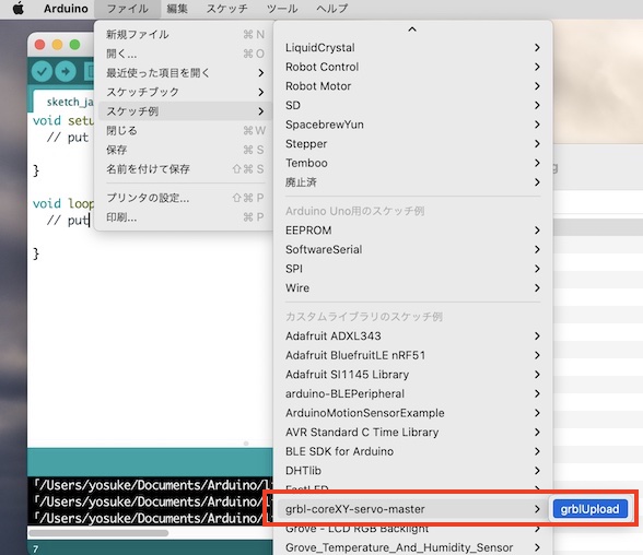
“grbl-coreXY-servo-master” is added as a sample sketch, and opne the sketch “grblUpload” in grbl-coreXY-servo-master.
「スケッチ例」に grbl-coreXY-servo-master という項目が追加されているので、その中の「grblUpload」スケッチを開きます。
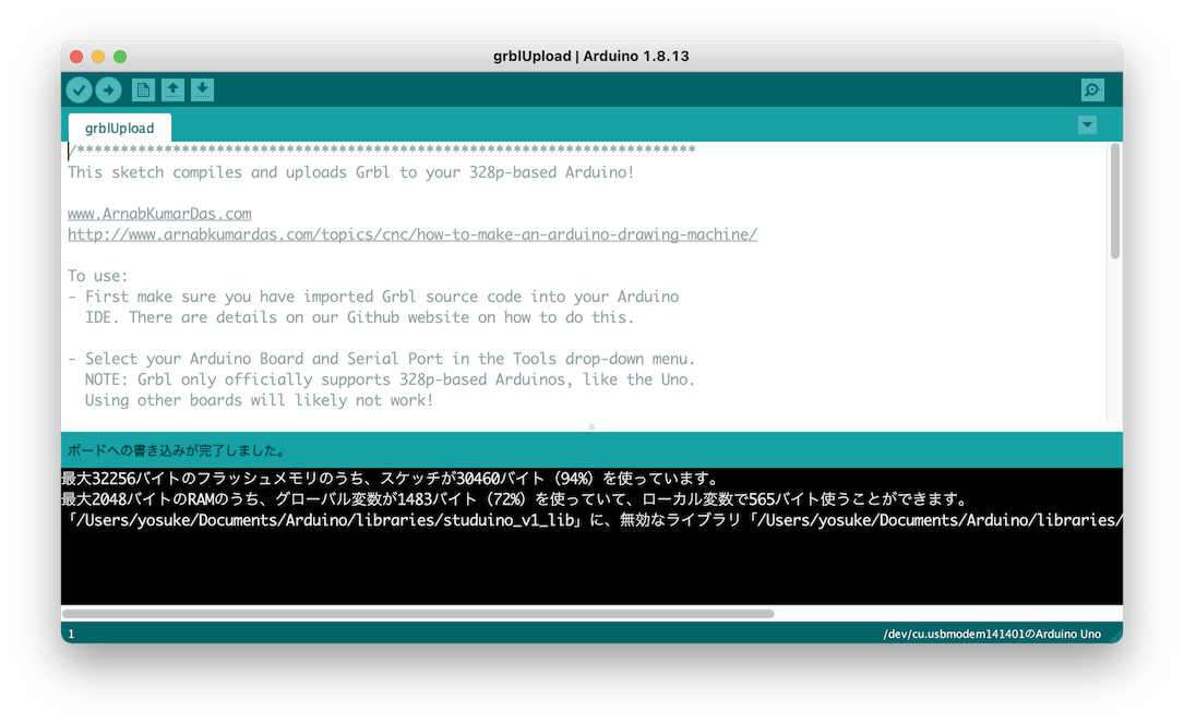
Connect Arduino UNO and PC, then write the sketch “grblUpload” into Arduino UNO.
Arduino UNO とPCをUSBで接続し、grblUploadをArduino UNOに書き込みます。
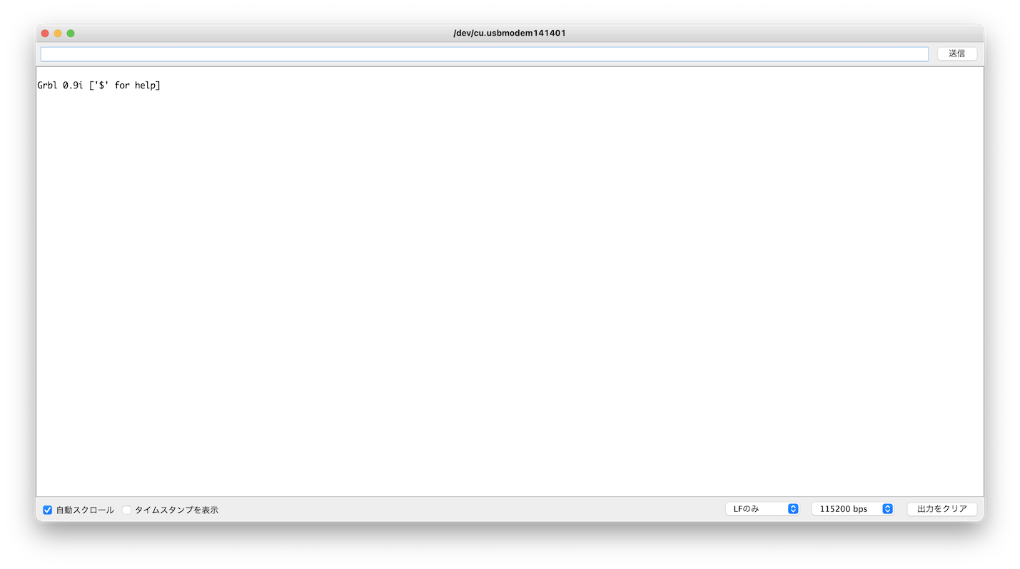
Open the Arduino Serial monitor and Operation check. Set boud rate in 115200bps, and you can see the following mesage “Grbl 0.9 [‘$’ for help].
動作確認をおこないます。Arduinoのシリアルモニタを開き、シリアル速度を115200bpsに設定します。起動初期に以下の通り「Grbl 0.9i [‘$’ for help] と表示されていることを確認します。
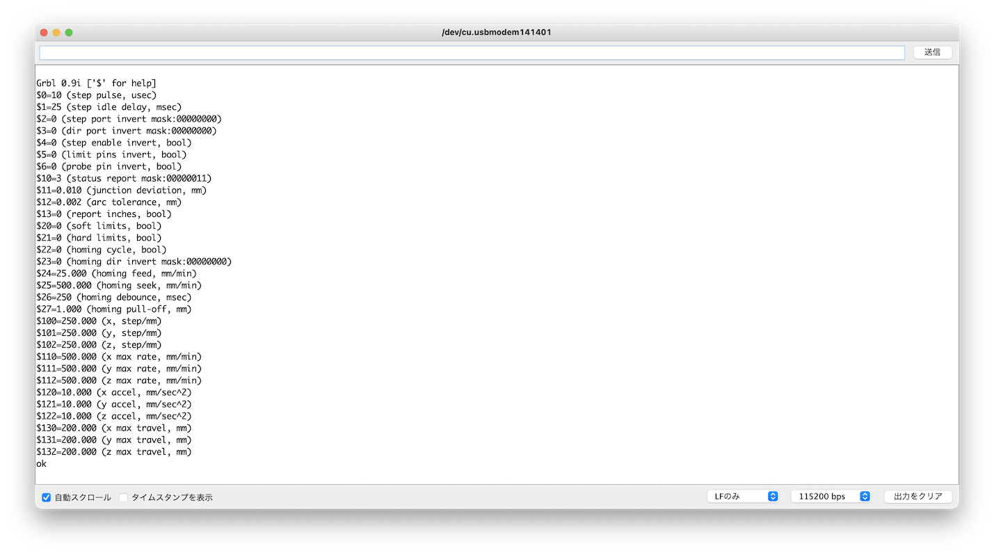
Next, type “$$” in the console of Serial Monitor. If you can see the following list of Grbl status message, you can confirm that the firmware works correctly.
続いて、シリアルモニタのコンソールに「$$」と入力します。すると以下の図のように、Grblの各パラメータの設定が表示されます。これが表示されていれば、正常に動いていると思われます。
Universal G-Code Sender#
Install “Universal Gcode Sender” to controll the drawing machine and send G-code data.
お絵描きマシンをPCからコントロールし、GCodeをマシンに送るためのソフトウェアとして Universal Gcode Senderをインストールします。
You can download Universal Gcode Sender Platform from [here]((https://winder.github.io/ugs_website/download/).
ココから、Universal Gcode Sender Platformをダウンロードしてインストールしてください。
Connect Arduino UNO to PC via USB cable, and turn on regulated power supply and give 12v to stepper motor driver. Then, you can start Universal Gcode Sender Platform.
Arduino UNOとPCを接続し、また安定化電源をONにしてモーターへ12vの電源を供給した状態でUniversal Gcode Sender を起動します。
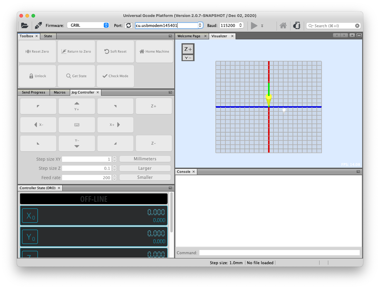
On the top of the software, thar following parameters should be set…
- Firmware = GRBL
- Port = Select Serial port that communicate with Arduino UNO
- baud = 115200
Then, press “connect” button. If everything is correct, the icon of “connect” turn into orange color and machine control buttons would be active.
画面上部のFirmwareは「GRBL」を、PortでArduino UNOとのシリアル通信ポートを、baud は「115200」を選択します。その上でconnectのアイコンをクリックします。うまく行くと connectのアイコンがオレンジ色に変わり、マシンコントロールの各種ボタンがアクティブになります。
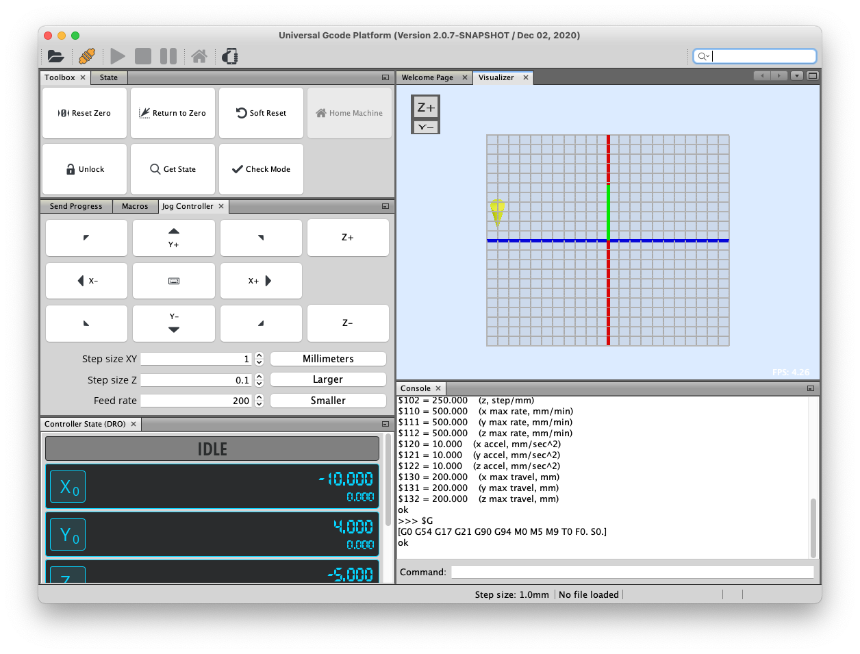
In Jog Controller, press top/bottom/left/right and confirm the endeffector has moved as preessed directions.
Jog Controller の上下左右のボタンを押したら、実際にマシンのエンドエフェクターが移動することを確認します。
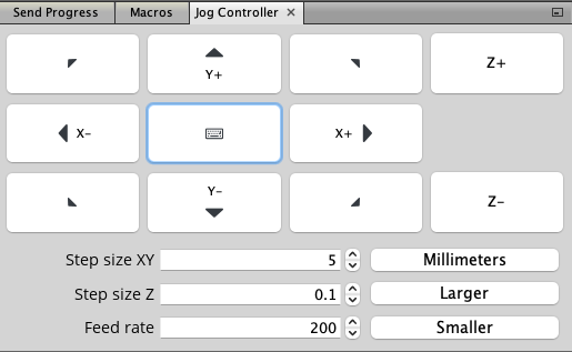
Change the rate of “step size XY”, and it would be changed the lengh that one press to move. The default parameter is “1 millmeters”.
Also, change the Feed Rate, and the speed that controlled by jog controller has changed.
この際、Step size XY の値を変えると、1回のボタンでの移動する長さを変えることができます。デフォルトは 1mmに設定されています。また、Feed rateの値を変えると、Jog Controllerで移動する際の速度を変えることができます。
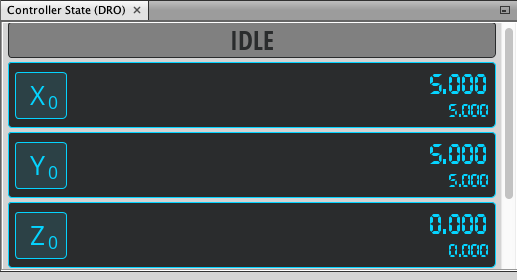
You can check the machine states on the panel of “Controller state”.
左下のController State の部分で、マシンの状態(ステータス、エンドエフェクタの位置など)を確認できます。
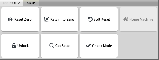
Toolbox on top left, you can do…
- “Reset Zero” set current endefeector position as origin.
- “Return Zero” move back endeffector to “origin” that set by “Reset Zero” (or the place when the machine has turned up).
左上のToolboxでは、マシンの設定変更やリセットを行うことができます。
- “Reset Zero”を押すと、エンドエフェクタの現在位置を原点に設定します。
- “Return to Zero”を押すと、”Return Zero”で記憶した原点(設定していない場合はマシン起動時の X=0,Y=0の位置)に戻ります。
When you turn on the machine, first, you should move endeffector to left bottom and press “Reset Zero” to set origin.
マシンを起動した時はReset Zeroボタンで、マシンの左下の位置を原点に設定します。
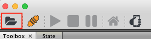
Click “Open” icon on the top-left corner and choose the g-code file that you want to open.
お絵描きしたいG-Codeのデータを読みたい場合は左上の「Open」ボタンを押して、該当のG-Codeを開きます。
Then, G-Code path are visualized on the right pannel “visualizer”.
G-Codeを読むと以下のような画面となります。右側のVisualizerにG-Codeパスが表示されます。
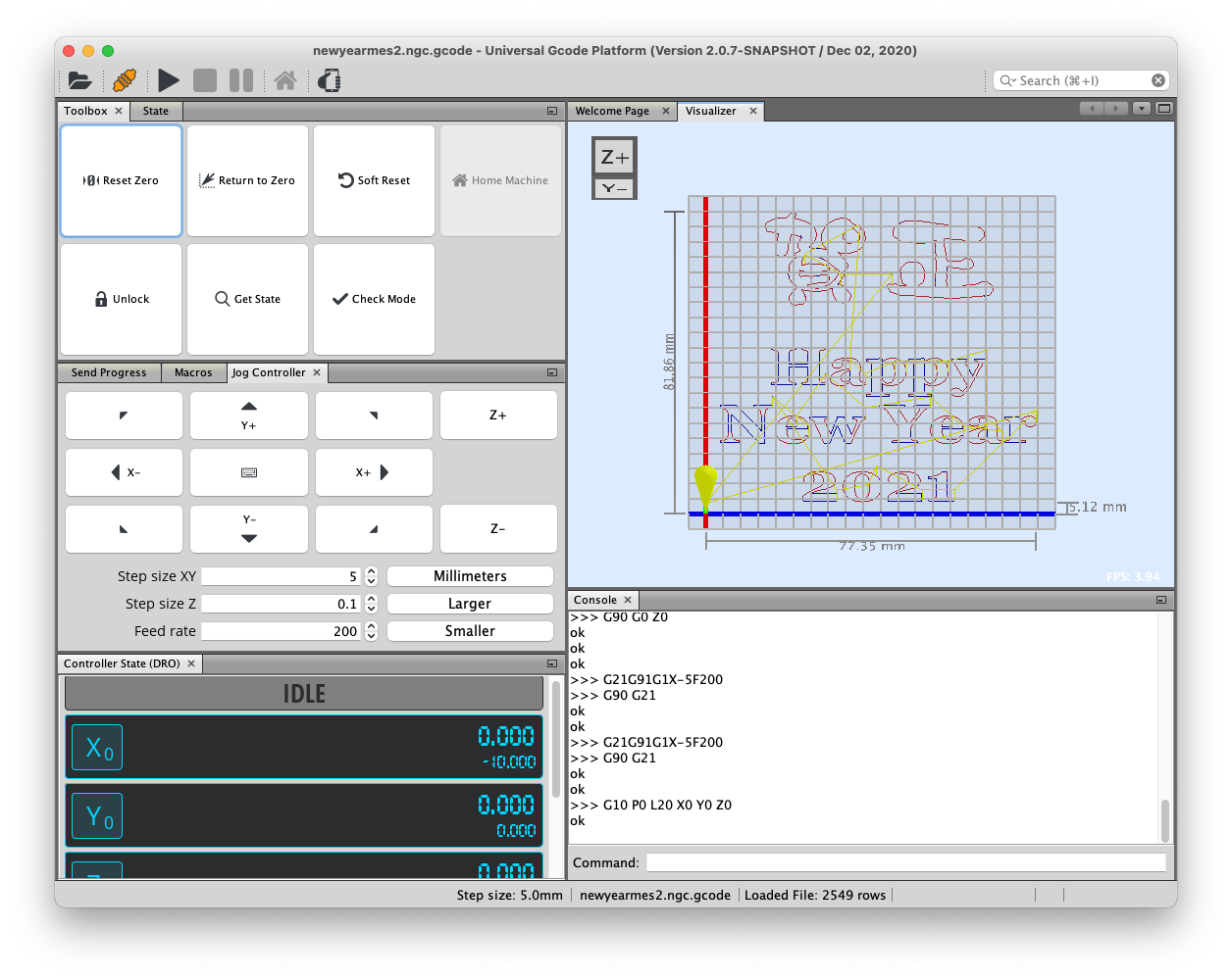
Move endeffector by JogController, and check whether G-Code data should be in the possible area for drawing. If you move the endeffector by JogController, the yellow point on visualizer also move.
JogControllerを使用してエンドエフェクタを動かし、G-Codeデータがお絵描き可能な範囲に収まっているかを確認します。Jog Controllerでエンドエフェクタを動かすと、あわせてG-Code Visualizer上の黄色い点も移動します。

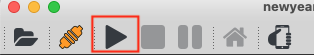
Click “Send” on the top-left, and the drawing would start.
準備ができたら、左上の「実行」ボタンを押します。するとお絵描きがはじまります。
Important Point in G-Code Generate#
When generating G-Code, “Path to G-Code” extension in Inkscape are used. There are a couple of ways to generate G-Code from 2D vector data.
G-Codeの生成の際には、よくInkscapeでパスをGcodeに変換する拡張機能が使われます。それに限らず、2Dベクター形式のパスからG-Codeを生成するやり方はいくつかあります。
However, when generating G-Code those ways, the command for Microservo up/down does not included. Therefore, when execute those G-code on Grbl firmware, the pen-up/down does not works.
ただ、通常の方法でG-Codeを生成してしまうと、Micro servoによるペンの上げ下げの命令が書き込まれませんので、GrblにてそのままG-Codeを実行してしまうとペンが降りてこない(書けない)あるいはペンが上がらない(ずっと描き続けてしまう)という状態になります。
To avoid this problem, we can use “GCodePostProcessor” program by Processing to insert the command for micro servo up/down.
これを回避するために、以下にまとめてある GcodePostProcessor というProcessingのプログラムを使用して、gcodeにマイクロサーボを実行するコマンドを挿入します。
First, download GcodePostProcessor program from below link, and open the program in Processing 3.0 IDE. It should be note the following procedures are instoructed in the below linked website “How to Control a Servo Using GRBL”, Step 5: Insert the Pen-Lift Commands. Please also check that website.
まず、以下のサイトからProcessingのプログラム GcodePostProcessor をダウンロードし Processingで開きます。なお、これ以降の手順は、以下のサイト “How to Control a Servo Using GRBL”の Step 5: Insert the Pen-Lift Commands にて紹介されていますので、あわせてそちらもご確認ください。
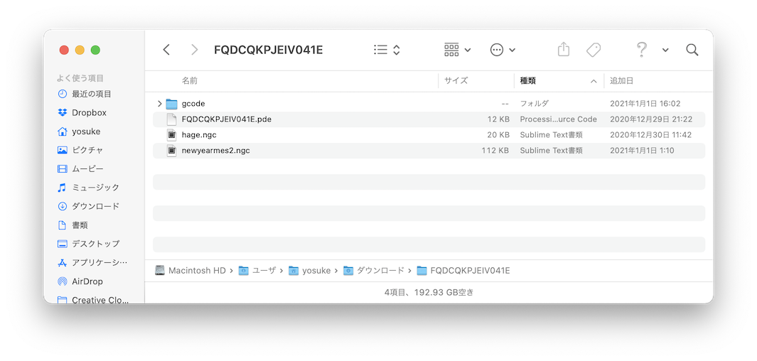
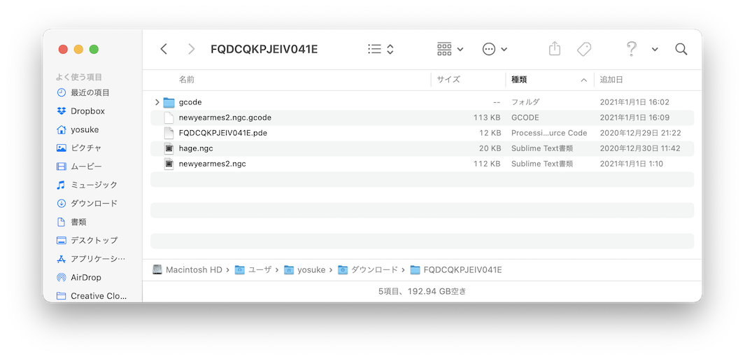
Move target G-Code into the same folder with the GcodePostProcessor program.
次に、以下の図のようにGcodePostProcessor.pdeがあるフォルダと同じ場所に、変換するGcodeを置きます。
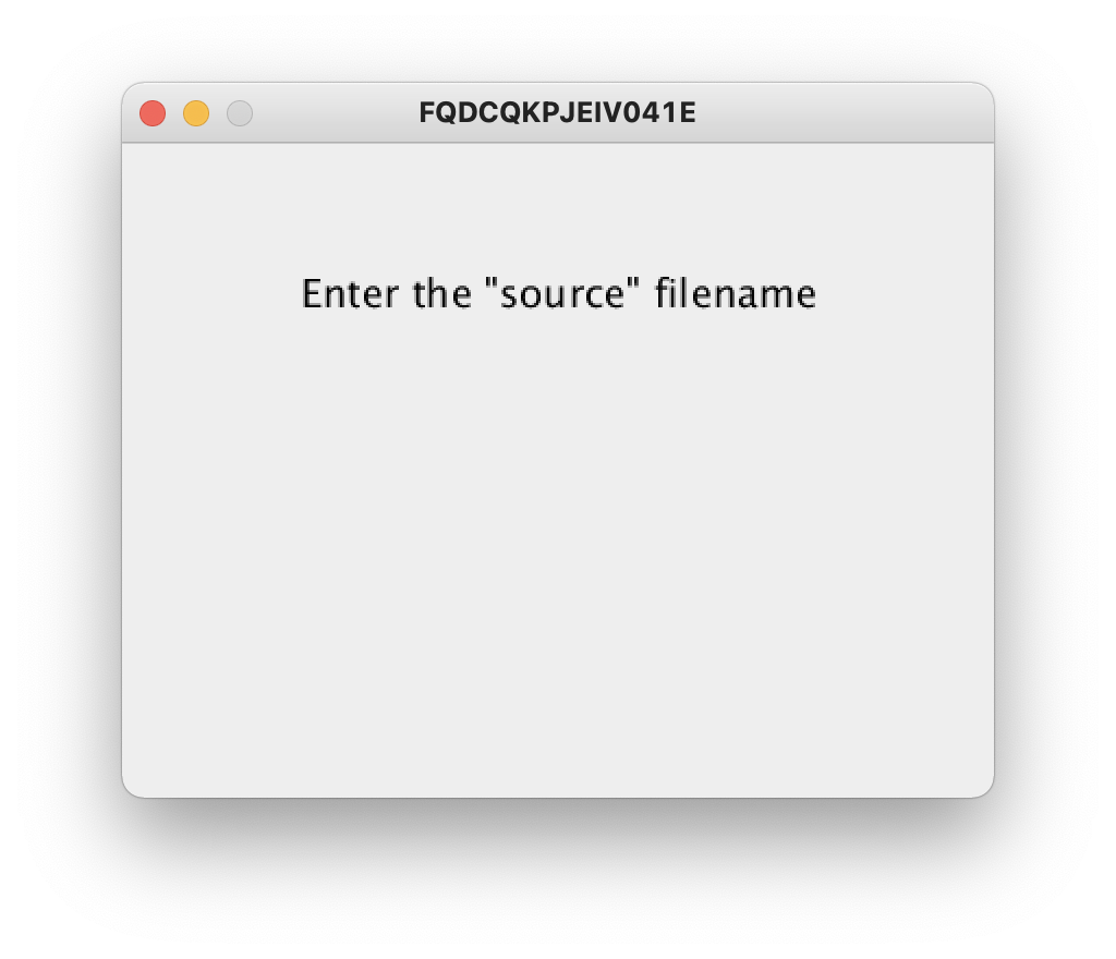
Run the Processing Program, and you can see the following view.
Processingにてプログラムを実行します。すると以下のような画面が表示されます。
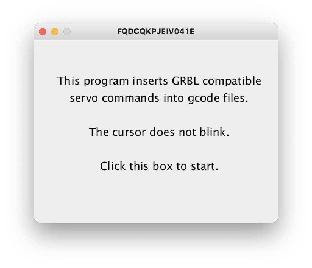
Click the view, then you can see the following view.
指示通り画面をクリックします。すると、以下の通り表示されます。
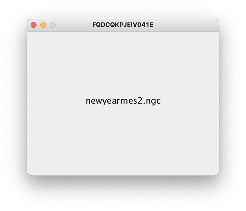
Enter the file name of targert G-Code. Here, I type the filename “newyearmes2.ngc”. After finished to type the filename, press Enter Key.
ファイル名を入力します。ここで入力するファイル名は、さきほど同じフォルダに置いたGcodeファイルです。ここでは newyearmes2.ngc と入力しています。入力したら Enterを押します。
Then, you can see the following view.
すると以下のように表示されます。
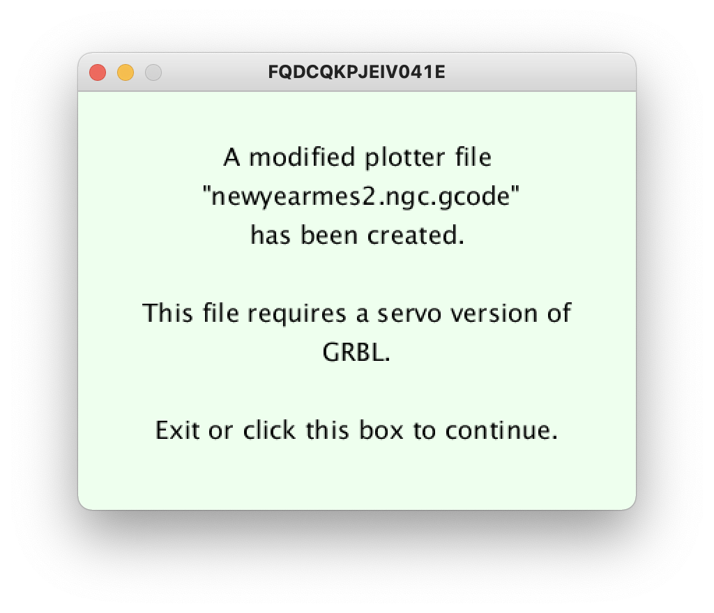
Check the foloder, and you can see the file “newyearmes2.ngc.gcode” was generated. You can open this converted G-Code file in the Universal G-Code Sender Platform, and execute it. Then, you can see the micro servo pen-up/down works.
さきほどのフォルダを調べると、”newyearmes2.ngc.gcode”というファイルが出来上がっています。これを、Universal Gcode Senderにて読み込み、実行すれば、正しくマイクロサーボのPen-upとdownが機能します。
Design Files#
STL file for 3D Print