tinyAVR 1-series#
Author : Jun Kawahara (FabLab Kamakura)
Date created : 6/29/2020
update: 2/9/2021 - megaTinyCore updating
update: 2/11/2021 - Kae-san confirmed Neil’s exact sample of hello.USB-UPDI.FT230X works fine.
update: 2/18/2021 - confirmed that hello.serial-FTDI.FT230X meets the requirement, add traces/interiors
update: 2/1/2022 - added D11C as a USB-serial bridge
Neil introduces new microcontrollers since Fab Academy 2020, one of which is tinyAVR from Microchip Technology.
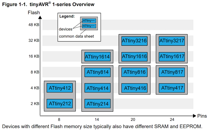
(image source: Getting Started with tinyAVR® 1-series)
tinyAVR 1-series can be programmed through the UPDI(Unified Program and Debug Interface). The classic ISP programmers cannot be used. So, you need a UPDI programmer.
A UPDI programmer is very simple, a TX, RX, and a suitable resistor. Connect TX from the PC UART to a 4K7 resistor. The other side of the resistor is connected to the PC RX and to the UPDI pin of the processor as shown in the image below.
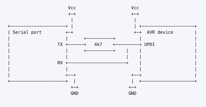
(image source: mraardvark/pyupdi)
updi programmers#
Neil introduces different types of UPID programmer. You have make one of these for an assignmnet in Electronics Production week, if you are going to use tinyAVR microcontrollers.
You need a FabISP as a programmer for conventional ATTiny microcontrollers.
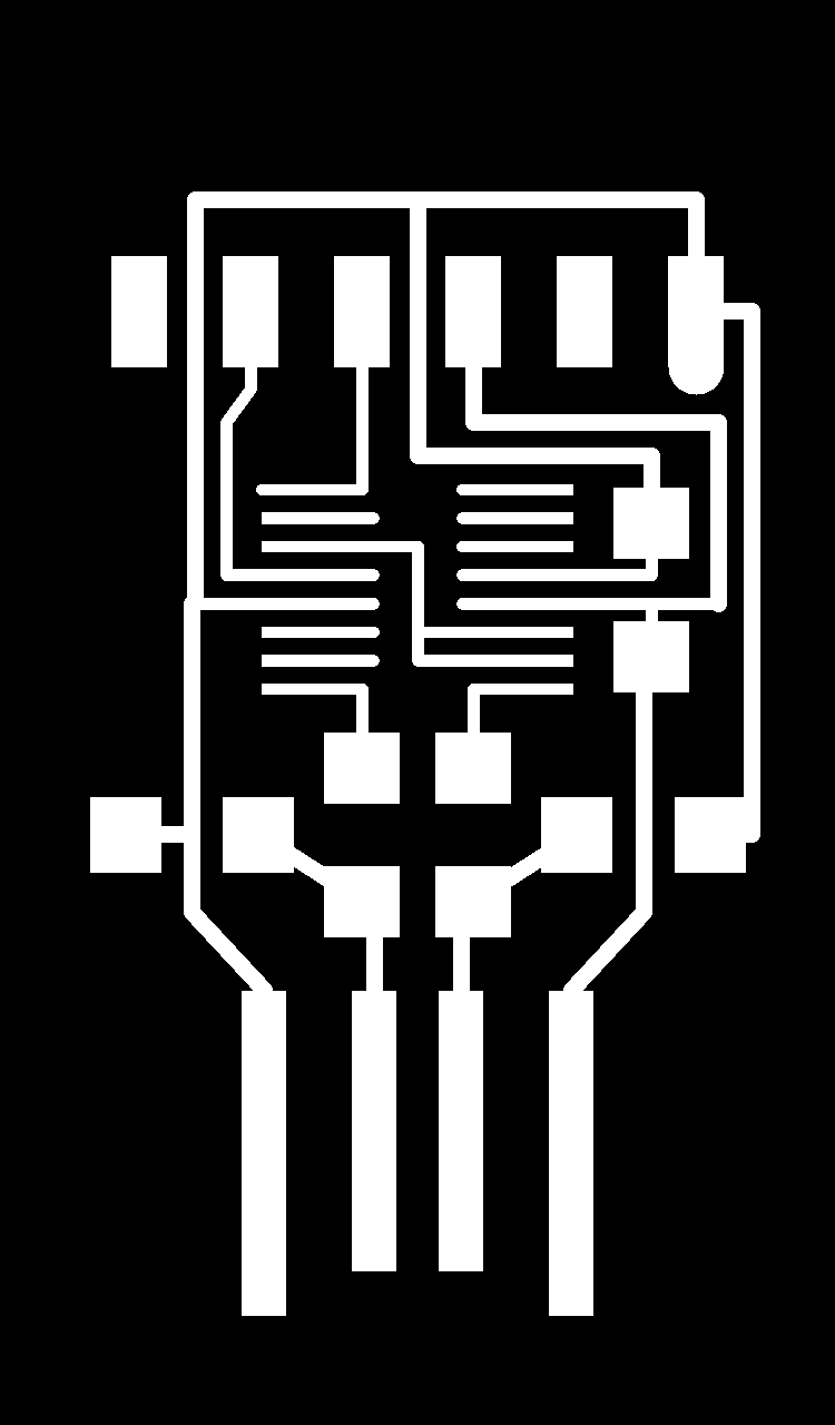
hello.serial-UPDI#
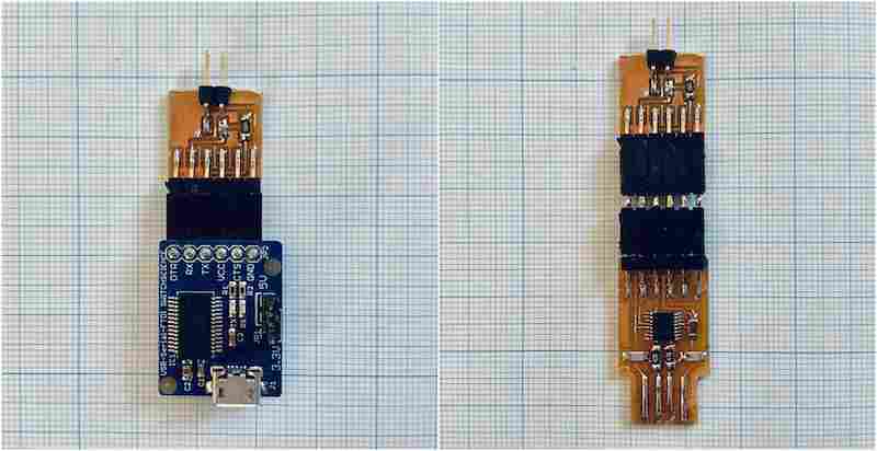
It’s FTDI-UPDI converter, and you still need a USB-FTDI converter to program a target board.
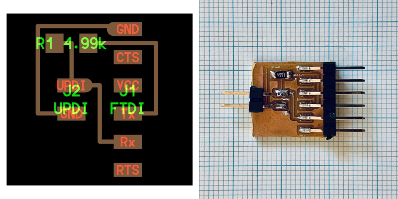
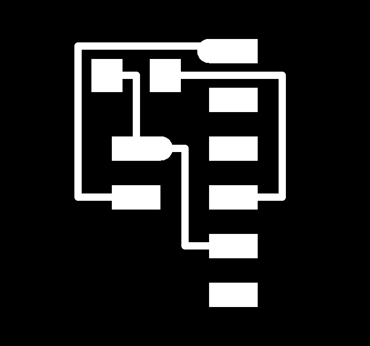
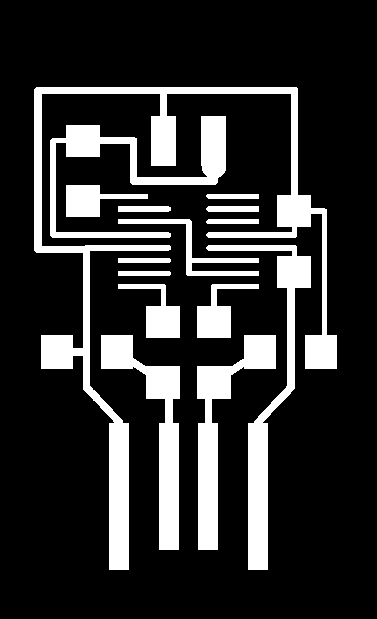
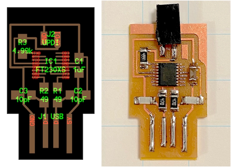
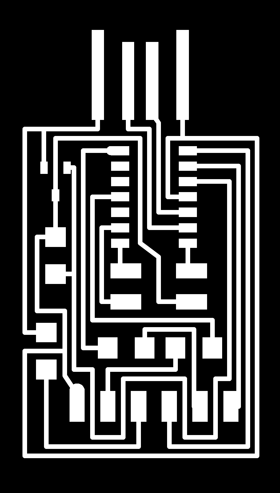
You can use it with an off-the-shelf USB-FTDI converter (image left), or Neil’s board, USB-FT230XS-serial board (right). - hello.USB-serial.FT230X: traces, interior
Info
In 2021 cycle, Neil said that this simple board met the requirement this week, but barely. I think it’s a good start for the first spiral, but strongly recommend that you make a USB-UPDI or a USB-D11C-serial.
hello.USB-UPDI.FT230X#
This programmer concludes USB-UPDI converter. You need a driver installed on your computer, but no firmware writing process is required.
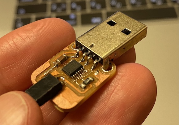
You may find it hard to solder tiny FT-230XS chip. If you are young enough, and have good pair of eyes, go give it a try.
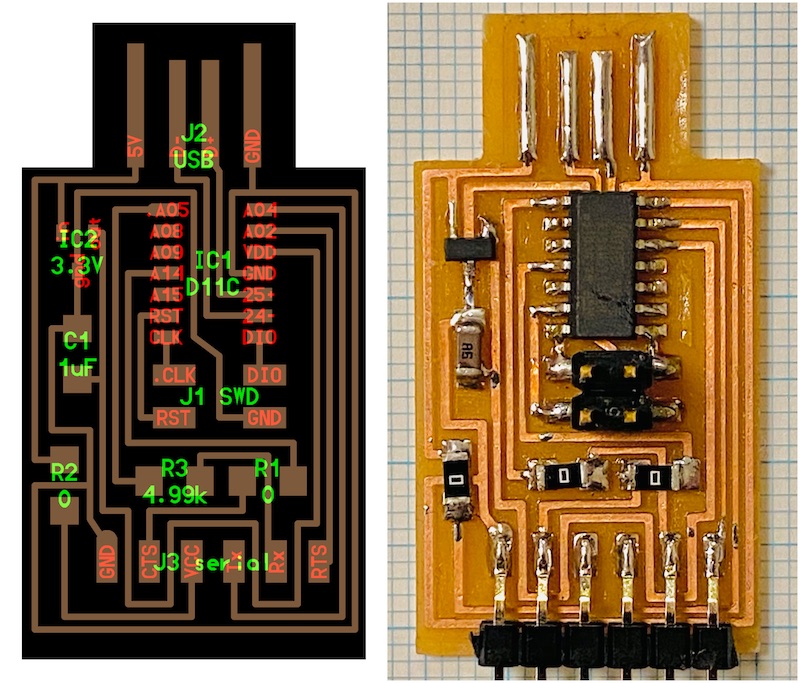
USB-D11C-serial#
This programmer uses an SAMD11C microcontroller as a USB-serial bridge. An arduino sketch makes it possible, so you have to burn a bootloader on it before uploading the sketch. It means you need a programmer tool, like Atmel-ICE. That is the difference between FT-230XS and SAMD11C.
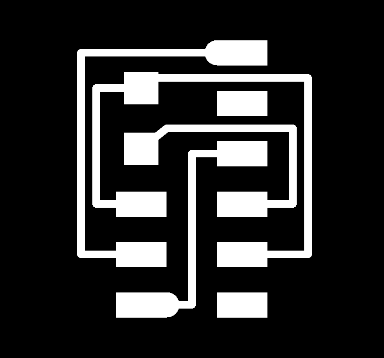
Soldering an SAMD11C is much easier than FT-230XS. - USB-D11C-serial: traces, interior
See this page on how to burn a bootloader and upload a sketch.
software#
install megaTinyCore#
Before programming a board, you have to install a board manager on Arduino IDE.
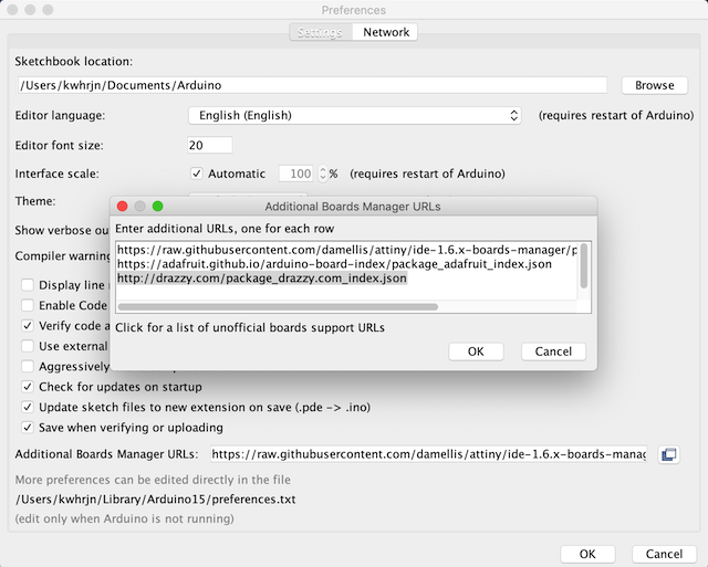
Launch Arduino IDE, open Arduino > preferences…
Add following URL to Additional Boards Manager URLs section.
http://drazzy.com/package_drazzy.com_index.json
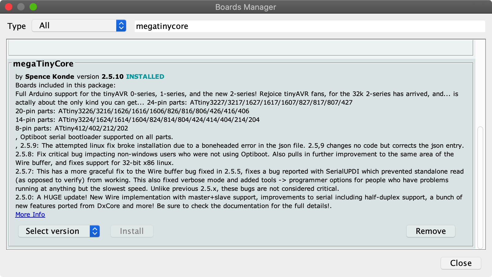
go Tools > Board > Board Mangers…, search megatinycore and install its latest version. 2.5.10 is the latest version as of Feb 2022.
Now you are ready for programming tinyAVRs!
install lsusb#
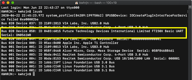
As an option, install lsusb, which make it easier to find whether your host PC recognize your programmer as an USB device.
brew install lsusb
Why doesn’t my pc recognize a programmer as a USB device?#
Before programming, make sure that your host PC recognize your programmer as a USB device. If your PC does, lsusb command will display like this.
So-called USBPCB is sooooo tricky. I recommend the continuity test. Check connection following paths.
- D+/D- of USBPCB to USP/USM of FT230X
- 5V/GND of USBPCB to VCC/GND of FT230
When they are fine, your pc is supposed to recognize your programmer. It is USBPCB which is wrong. My recommendations are,
- applying solder iron on USBPCB pads
- using shim (a stack of tapes) on the backside of USBPCB
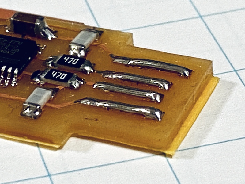
Or you can make your USB connection stable by modifing like this.
programming examples#
ATtiny412#
blink
-
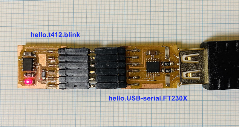
I assume that you already have made a hello.t412.blink, and hello.USB-serial.FT230X board.
Connect your computer with hello.USB-serial.FT230X, and make sure that your host PC can recognize it as a USB device.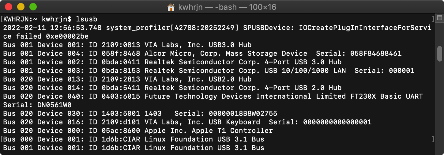
-
download hello.t412.blink.ino, open it with Arduino IDE.
-
connect your computer, hello.USB-serial.FT230X, and hello.t412.blink board
-
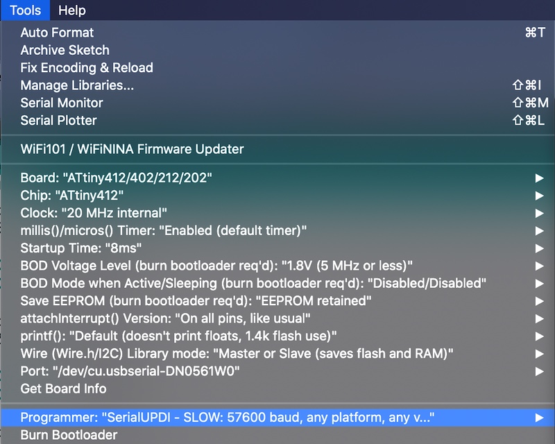
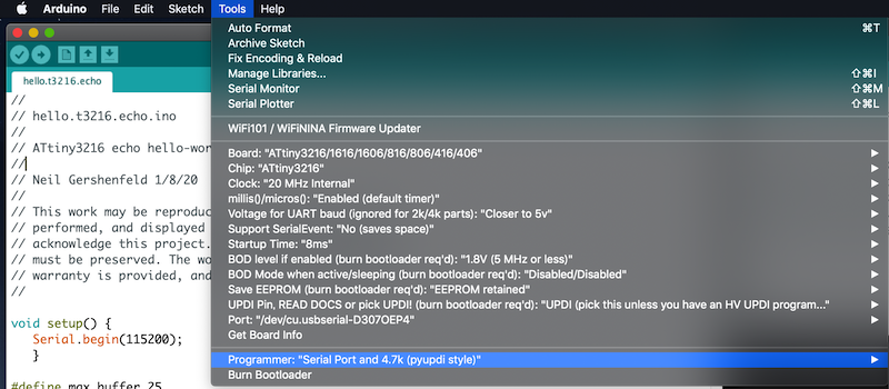
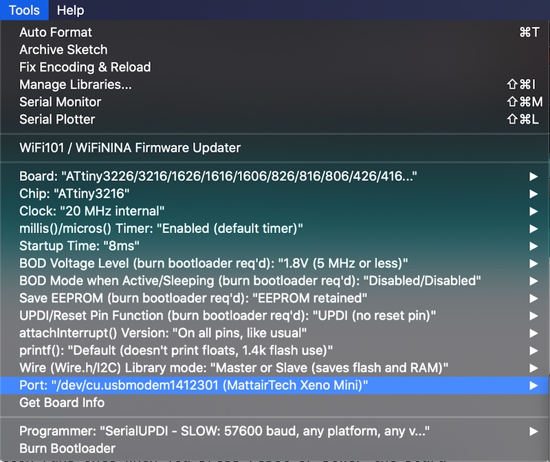
Inside Tools menu, select Board, Chip, Port and other options. Also remember to select a Programmer: “Serial Port and 4.7k (pyupid style)” or SerialUPDI - SLOW 57600 baud, any platform, any voltage, any adapter.
-
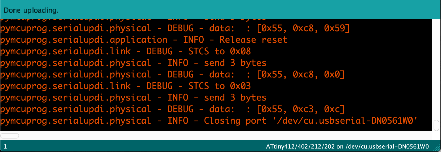
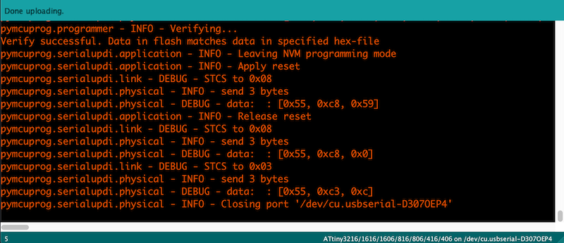
Then, upload your sketch. After long long verbose, you ill get Done uploading message on your window. An led on your board must be blinking now.
NeoPixel
Everyone loeves NeoPiexel, but it seems that ATtiny doesn’t get along with NeoPixel libraries, such as Adafruit_NeoPixel, FastLED, and tinyNeoPixel. API is different from Adafruit, but a library, FAB_LED, works fine with an ATtiny412.
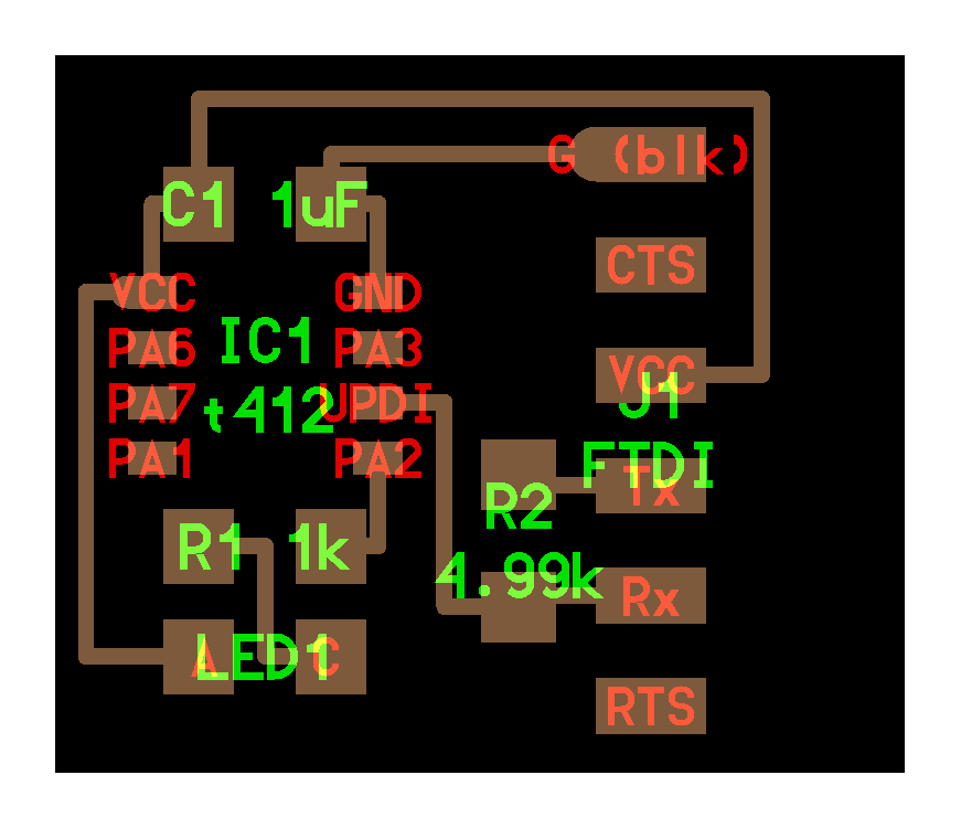
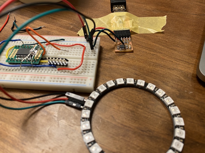
I frankensteined a hello.t412.blink board. A NeoPixel ring(24 LEDs) is powered from USB, and its signal line is connected to ATtiny412’s PA1.
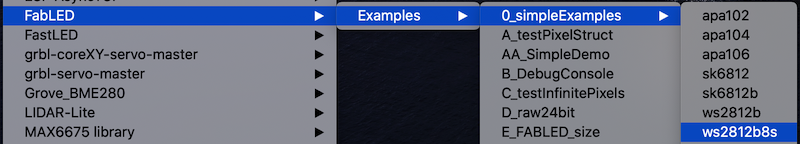
Opne File > Examples > FabLED > Examples > 0_simpleExamples > wb2812b
As I mentioned, a ring has 24 LEDs, a signal lines is connected PA1 of ATtiny412, so the sketch should be modified as below. Change its brightness as you wish.
// Declare the LED protocol and the port
ws2812b<D,1>  strip;

// How many pixels to control
const uint8_t numPixels = 24;

// How bright the LEDs will be (max 255)
const uint8_t maxBrightness = 255;
ATtiny3216#
-
download hello.t3216.echo.ino, open it with Arduino IDE.
-
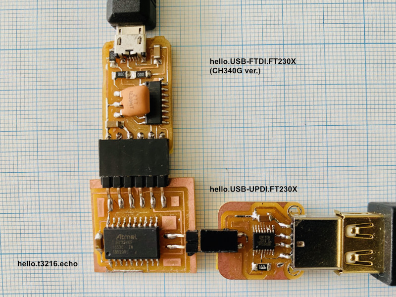
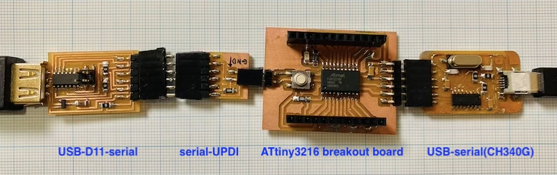
Connect your ATtiny3216 board with a hello.USB-serial.FT230X and a hello.USB-UPDI.FT230X. In an image below, I used a USB-UART converter with CH340G, an FTDI-alternative chip.
-
Inside Tools menu, elect Board, Chip, Port and other options. Also remember to select a Programmer: “Serial Port and 4.7k (pyupid style)” or SerialUPDI - SLOW 57600 baud, any platform, any voltage, any adapter
-
Upload the sketch. After Uploading done, You are now ready to communicate with your board.
 Type command like below. USB-serial converter depends on yours.
Type a byte character. It is successful when the typed character is echoed back on your terminal. Congratulations.
Type command like below. USB-serial converter depends on yours.
Type a byte character. It is successful when the typed character is echoed back on your terminal. Congratulations.$ python -m serial.tools.miniterm /dev/tty.wchusbserial141230 115200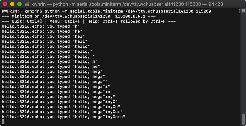
ATtiny3216 breakout board#
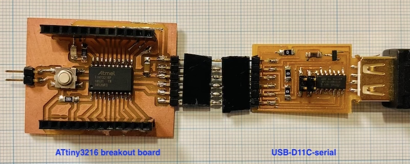
Examples below uses ATtiny3216 breakout board with an LED and a button, and [USB-D11C-serial] as a UPDI programmer and a USB-serial bridge.
blink
- In Arduino IDE, open File > Examples > 01.Basics > Blink.
- Define on which pin an LED is connected. In this case it’s on pin 16. At the begining of a sketch before setup function, add the declaration like,
#define LED_BUILTIN 16 -
Connect a breakout board with a USB-D11-serial(as a programmer) and a USB-serial(as power supply).
3. Inside Tools menu, elect Board, Chip, Port and other options. Also remember to select a Programmer: “Serial Port and 4.7k (pyupid style)” or SerialUPDI - SLOW 57600 baud, any platform, any voltage, any adapter -
Upload the sketch, and an LED will blink.
blink with button 1. Connect a breakout board with a USB-D11-serial(as a programmer) and a USB-serial(as power supply) as shown above.
- In Arduino, Open File > Examples > 02.Digital > Button
- Modify a sketch based on which pin an LED and a button are connected. In this case LED is on pin 16, and a button is on pin 0.
// constants won't change. They're used here to set pin numbers: const int buttonPin = 0; // the number of the pushbutton pin const int ledPin = 16; // the number of the LED pin - Upload the sketch, the an LED is on. LED will only stay turned on unless the button is pushed down.
echo 1. Connect a breakout board with a USB-D11-serial(as a programmer) and a USB-serial(as power supply).
1 | |
- download hello.t3216.echo.ino, open it with Arduino IDE.
- Inside Tools menu, elect Board, Chip, Port and other options. Also remember to select a Programmer: “Serial Port and 4.7k (pyupid style)” or SerialUPDI - SLOW 57600 baud, any platform, any voltage, any adapter, then upload the sketch.
-
Reconnect your ATtiny3216 board with a USB-D11C-serial as a USB-serial bridge also as a power supply.
Type command like below. USB-serial converter depends on yours.
Type a byte character. It is successful when the typed character is echoed back on your terminal. Congratulations.$ python -m serial.tools.miniterm /dev/cu.usbmodem1412401 115200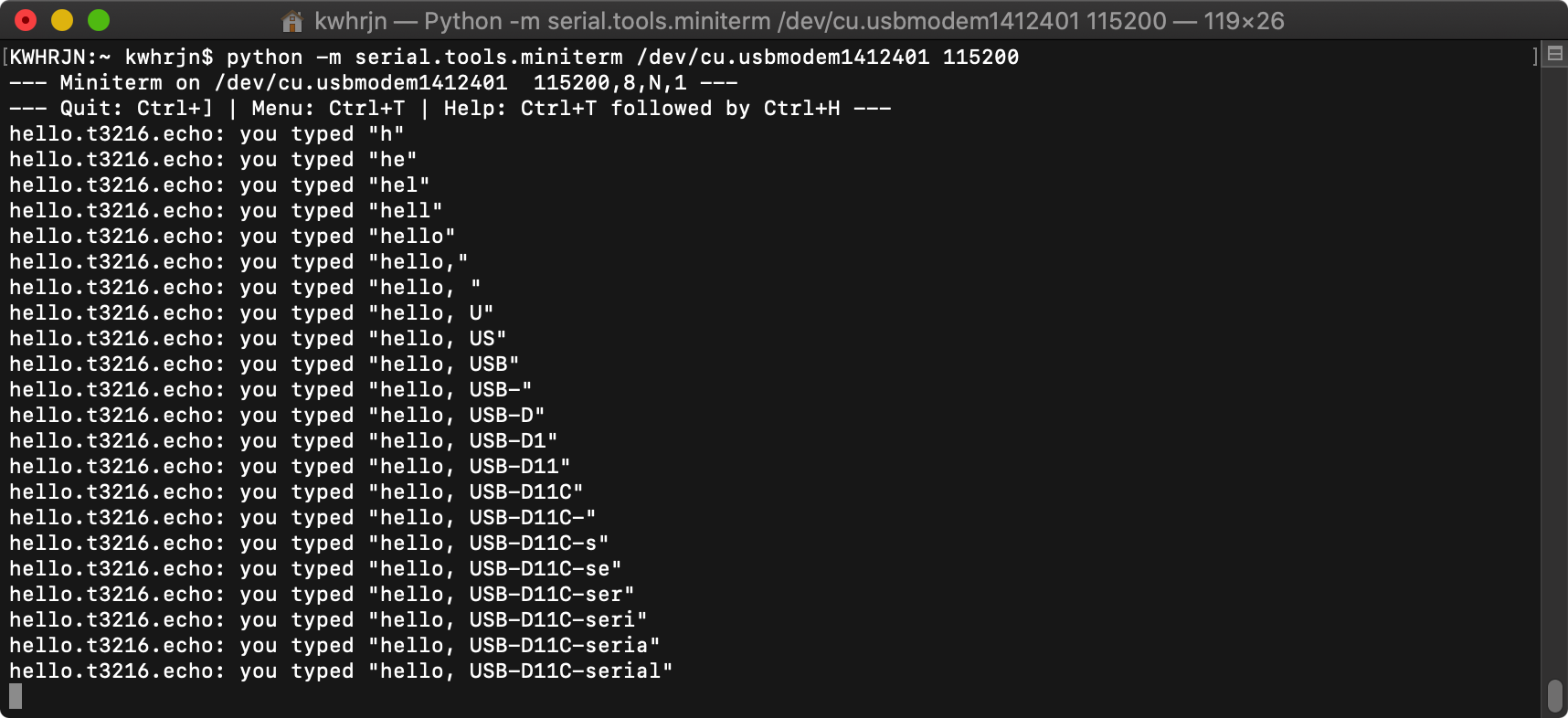
references#